¶ Triangulator
The triangulator is the surface-building function inside PCS. It can build a 3D TIN network from vectors and point clouds. These TIN networks can be used as surfaces and exported to DXF/DWG as 3D faces. PCS also offers various operations using these TIN surfaces.
The default format for PCS TIN surfaces is .TRI and the software consider them as vectors.
To use the triangulator, a minimum of one point cloud or vector file shall be opened in the project. It is also highly recommended to avoid using 2D elements and shape files during the triangulator process as they will create spikes in the result surface model. Users can use only those elements which are loaded into the project. It is not possible to browse files from the Triangulator window.
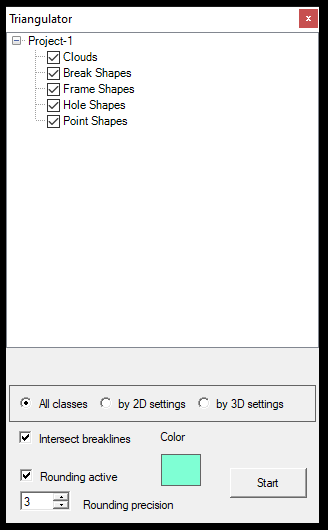
As users can see from the settings panel, the triangulator can utilize the following objects:
- Clouds - Point clouds, using all classes, 2D classes (turned on for 2D view) or 3D classes (turned on for 3D view). Right-click on the clouds and select Add Clouds to select clouds loaded into the project or remove the already selected clouds.
- Break Shapes - Polyline-type SHP files will serve as break lines for the surface building. All elements in the selected SHP files will be used. Polyline and Polygon types of SHP files are accepted. Right-click on the Break Shapes and add or remove SHP files from the project.
- Frame Shapes - This is the boundary where users would like to build the surface. This boundary shall be a 3D boundary as well, so it's recommended to drape it to the point cloud (if possible) to avoid spikes. Only Polygon SHP files are accepted. Right-click on the Frame Shapes and add or remove SHP files from the project.
- Hole Shapes - Use this SHP to exclude some areas WITHIN the frame area. The result will be a “doughnut” surface. Only Polygon SHP files are accepted. Right-click on the Hole Shapes and add or remove SHP files from the project.
- Point Shapes - Use this to add the point type of SHP-s. From the triangulator's perspective, the point, text, or block SHPs (as we would refer to them for CAD-based extractions) are the same, all considered point SHPs. Right-click on the Point Shapes and add or remove SHP files from the project.
Intersect breakline - This setting will intersect all polylines that diverge in the space but have an intersection in 2D. It will insert a vertex for those places. It is recommended to use this function, but it is even more recommended to select only those polylines with a proper topology.
Rounding Active - This checkbox will round all coordinates to the giver rounding precision, excluding small shiver polygons because of more decimals. It is recommended that this function be done well.
Color - The output triangulated network's colour.
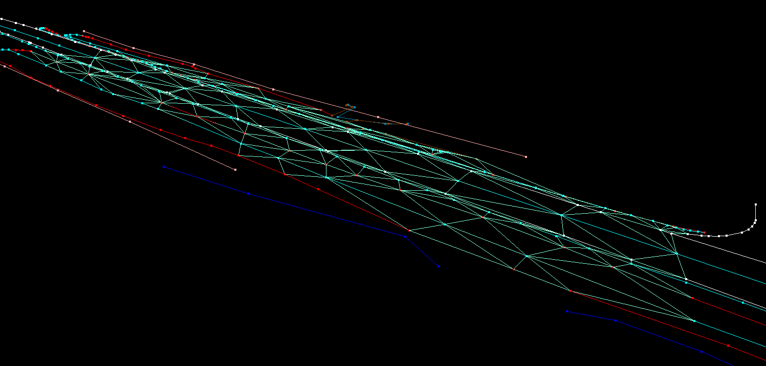
After pressing the start button, the software will generate the triangulated network. If point clouds - especially not reduced-density ones - are being used, the process might take a while. Please note that there is no progress bar; the software might seem stuck during the process. When it is finished, a pop-up window will appear.
The triangulator will create the .TRI file inside the Project Explorer/Vectors. If the user right-clicks to the triangulated file, the following options will be available:
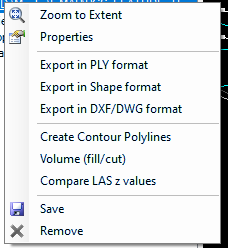
Zoom to Extent - Zoom to the extent of the triangulated surface.
Properties - Properties of the triangulated surface. Users can modify the colour of the triangle lines if the surface triangles are filled and which fill colour shall be used. Some basic information can be accessed here, like the number of triangles, average edge length, and XY extent coordinates.
Export in PLY format - Export the triangulated surface to .PLY format for further use.
Export in Shape format - Export the triangles to a polygon shape format. Please note that a more significant area might contain as many triangles, which might be too much for a SHP file. We recommend using this function for smaller files, up to a few thousand triangles.
Export in DXF/DWG format - Export the surface as 3D faces to a DXF or DWG file format. This export does not require any attribute settings for the DWG (as the triangulated file has no attribute).
Create Contour Polylines - This function will create contours from the surface based on the user parameters. See the settings below.
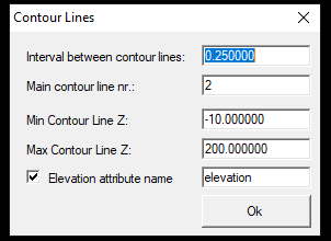
Users can set the step level using the contour settings, and the elevation range between the contours will be generated. The created contour file will be a polyline SHP, and the users can include the elevation value as an attribute. If the users would like to export the contours to a DXF/DWG file, append the DXF attributes from the project manager to this SHP file and assign the proper attributes.
Volume Cut/Fill - This function allows the user to specify an elevation, and the software will create an XY plane at this elevation and intersect the surface with this plane to provide the cut and fill values. This function can be used for depo calculation.
Compare LAS Z values - This function allows the user to compare the surface against the point cloud. Please find the detailed description of this tool by clicking here.
Save - Save the .TRI file at the designated location.
Remove - Remove the triangulated surface from the project.
¶ Known Bugs
- In case of a topologically incorrect drawing, the Triangulator might crash. It is highly recommended that the Topology Tools be used to build the surface or ensure troper topology in another way.