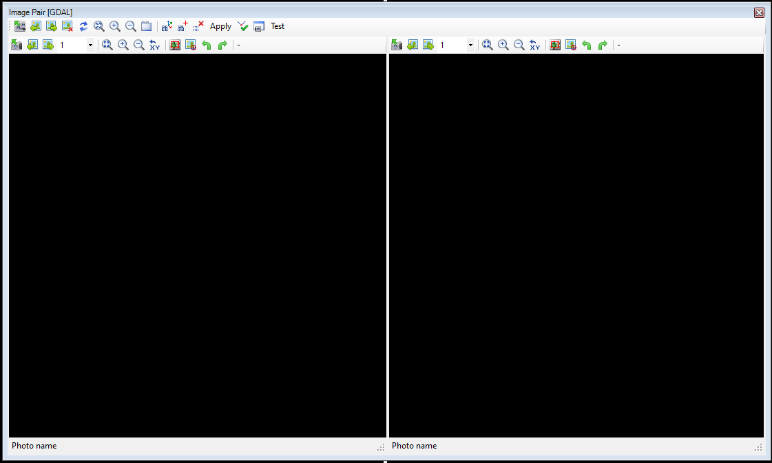
¶ Image Pair View
The Image Pair View (or Image Pair Window) is a separate work window inside PCS. It does allow the user to identify points based on photogrammetric measurements from geophotos. If geophotos are loaded into the project using the Project Explorer, the Image Pair View can be started from the Standard toolbar in the Main Window. The Image Pair View is dockable.
The Image Pair View allows the user to select a left and a right image. As the loaded images are calibrated, choosing the same point on both images enables the software to calculate the coordinates of the point and forward this point to the active command, like the new element command. This can be very useful if the camera is located further from the laser (for example, the camera is placed higher than the laser) and obtaining a coordinate is impossible in another way. Please keep in mind that the accuracy of the measured point cannot be better than the system's original accuracy, and the camera sensors might have a different accuracy class compared to the lasers.
The Image Pair Window has a main toolbar at the top and a smaller toolbar for each photo window. The photo window toolbars are identical, which will only be explained once. We recommend keeping the image pair window together with the 2D or 3D window, as it shall be possible to select a photo from one of the views.

The description of the main toolbar tools is the following:
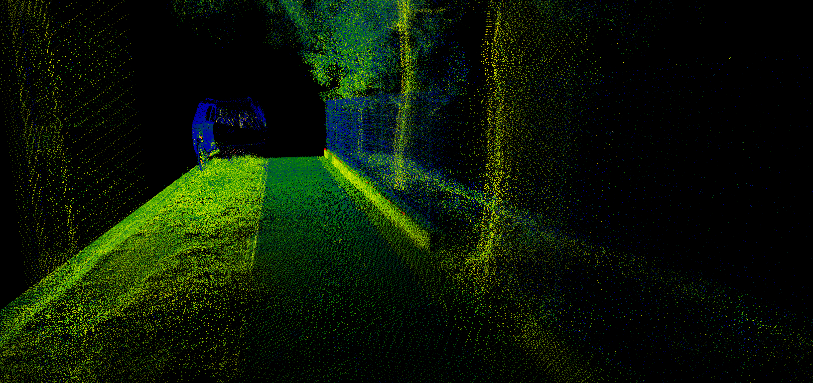
- L+R photos - This tool allows the user to pick the left and right images. The image can be selected directly by clicking the geophoto marker in 2D or 3D view or clicking on the point cloud, where the software will try to find the closest photos.
- Previous/Next Geophoto - The software steps to the next photo for both windows. This is handy when using MLS datasets, but other datasets like SLAM or TLS might not result in the designated photo.
- Remove Photos - Clears both photo windows.
- Swap photos - Swap the left and right photos.
- Fit - Fit the current photo to the window size.
- Zoom in/out - Zoom in and out on both photos.
- Turn on/off magnify window - Turn on a magnifying window to the top left corner of each photo window, showing the cursor's environment as magnified, helping the user pinpoint the target on the photos.
- Finding two pictures on which the 3D target point can be found - This tool will load two images on which the rotation centre (3D target point) is visible.
- Finding two pictures on which the 3D marker can be found - This tool will load two images on which the 3D marker is visible.
- Restore image - Remove all markers from the image placed by the user.
- Apply - The software calculates the coordinates based on the selected points and sends them back to the main windows so the active tool can utilize it. For example, if the active SHP is a polyline, and the New Polyline Element command is active, this point becomes the start point of the polyline. In that way, the measured point can be used for vector extraction.
- Calculate - Calculate the position of the placed markers. The result will be visible in a new window.
- Screen Capture - Creates a screenshot from the Image Pair Window.
- Test - Testing feature for the Image Pair View. Please do not use it without prior instructions. In general, pressing the button will not do anything.

The description of the tools in the photo windows is the following:
- Select photo - Select the left or right photo.
- Previous/Next Photo - Move to the previous or next photo for the current photo window.
- Step Count Dropdown - Set the step rate for the prev/next image.
- Fit - Fit the current photo to the photo window size.
- Zoom in/out - Zoom in and out in the selected photo window.
- Toggle Overview Window - Toggle the "minimap" for the photo to the top right corner to see which part of the image has been inspected.
- Rotate image left/right - Rotate the image 90° left or right.
- Image adjustments - Set the brightness, contrast and gamma for the image.
¶ Usage of the Image Pair Window
Start the Image Pair View. It is recommended to use it on a separate screen. The Image Pair View is an additional tool to give coordinates to an active tool, like new elements, move elements, etc.
IT IS MANDATORY TO HAVE AN ACTIVE TOOL IN THE MAIN WINDOW, OTHERWISE THE COORDINATE CANNOT BE TRANSFERRED!
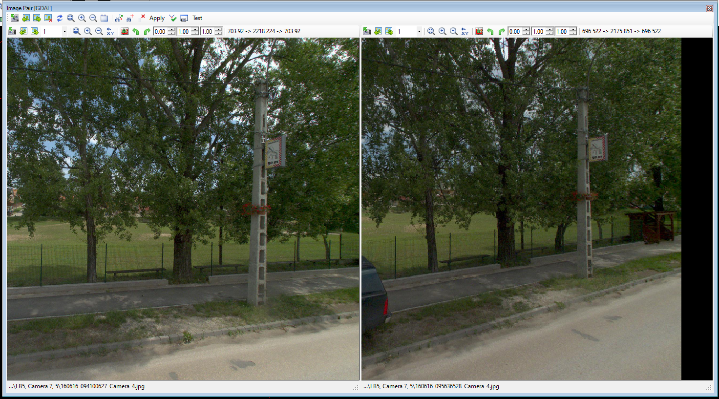
After starting the Image Pair Window, select a location or two images to have 1-1 images for each windows where the feature that you need is visible.
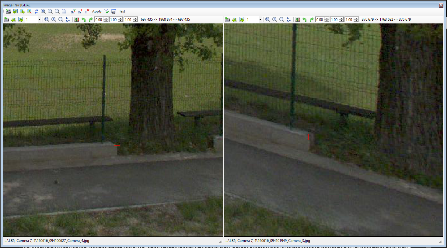
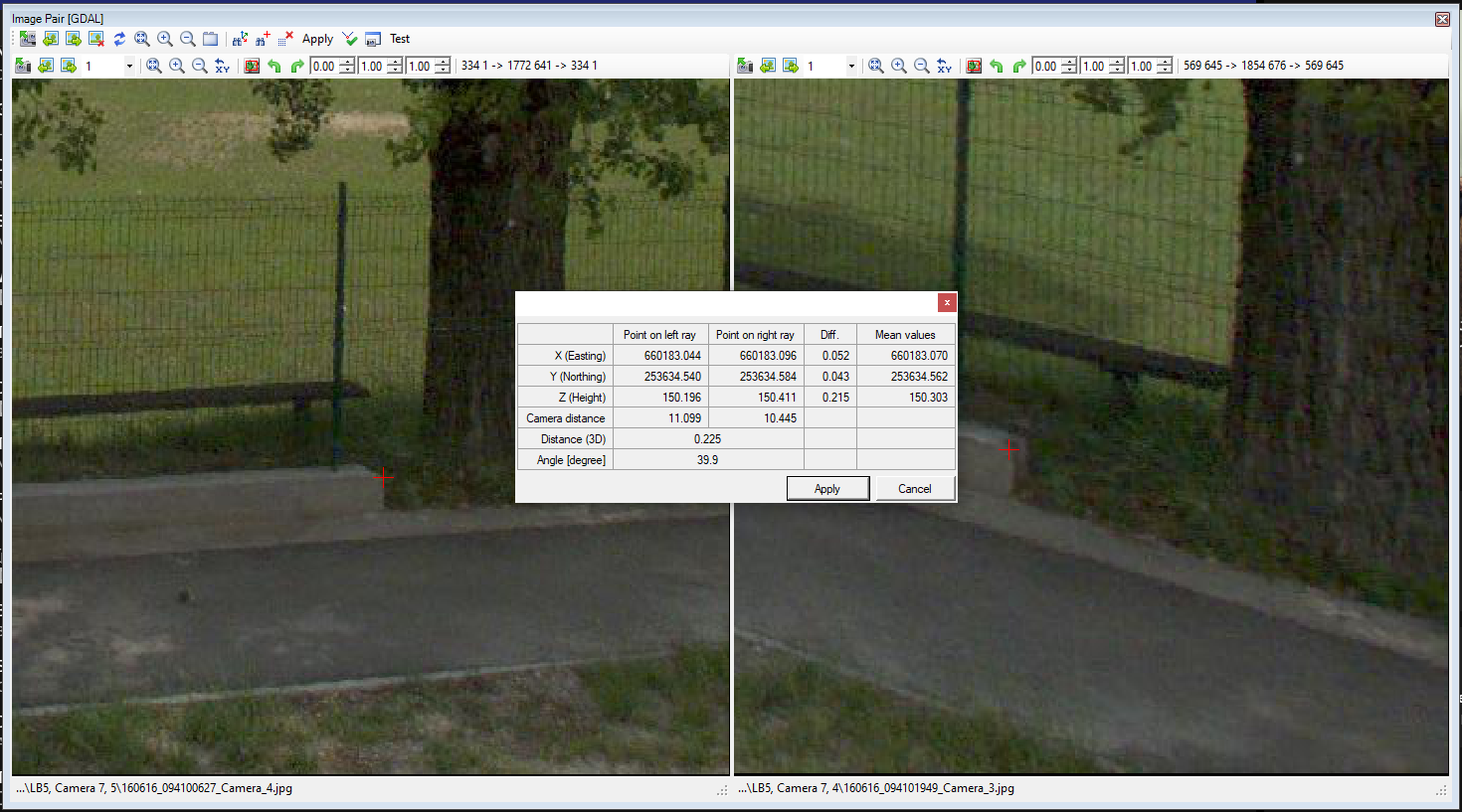
In this given example, a point at the fence base will be extracted using this function. As mentioned, it is mandatory to have an active command, where the Image Pair View can transfer the coordinates. If there is an ongoing extraction for a polyline or polygon, the selected points will become the next point in the polyline/polygon.
To perform the measurement, select the same location in the 2 images. It is better to have two separate angle images of the same object. The user can re-pick the images using the image selector in the Image Pair Windows. Please note that it may seem that upon selecting a new image, the already existing linework “disappears”, but it does not; just the view does not refresh instantly.
To measure a point using the image pair view, zoom into the point you are seeking, and double-left click on the location that you wishes to measure on both images. Upon double-clicking the location, a red cross will appear at the designated place. The point can be adjusted if the user double-clicks again.
After the points are selected, press the ‘Calculate’ button. This will calculate the point coordinates based on the left-right image points. The system will calculate the mean value for both points and display the errors as well.
If the user is not satisfied with the results, press cancel and re-pick the points, and press calculate again for refining the results. If the result is acceptable, press the apply button, and that will send the coordinate back to the active tool.
As described at the top of this page, the function accuracy is highly dependent on the original accuracy of the image calibration and the accuracy with which the user uses to select the points on the images.
The tool can be used with any type of SHP files or any modification tools that can modify a location (new or existing elements).