¶ Design File Geodatabase
This functionality allows the users to design their own File Geodatabase (FDB) from scratch. Please note that the function is still in development; the final user interface and functionality will be described here later. This article represents the current status of the FDB designer as of May 2024. Some SHP file-related appellation is also used here as the functionality is similar to that of the FDB, and it helps the user understand the topic.
The design FDB functionality can be accessed by right-clicking on the Project Explorer - Vectors level and selecting the Design File Geodatabase option. The tool will open the designer window.
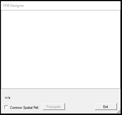
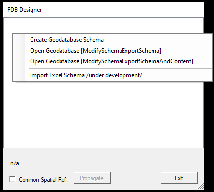
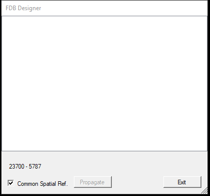
The designer - by default - is empty. Upon right-clicking on the white area, the user can specify if a new database shall be designed or an existing one shall be modified (including the data inside the DB). In the future, Excel schema import will also be possible, but this option is still in the early stage of development.
In this article, we discuss the creation of a new schema. Modification uses the same tools as the creation, so the modification is not discussed separately.
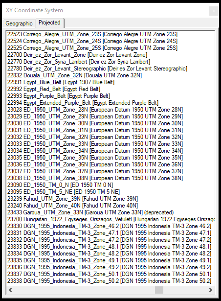
If a new schema is designed and an option, we recommend checking the Common Spatial Ref. checkbox, as it will apply the selected projection for all tables. After checking this checkbox, the software will prompt the user to the horizontal projection, the projection's parameters, and the vertical projection. Our users should get to know the EPSG codes of the used projection, as it is the easiest way to find the projection from the list, as no search option is available. The horizontal projection page has two tabs: geographical projections and projected projections. To select a projection, double left-click on the selected line.
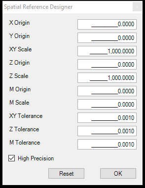
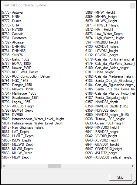
After the projections are set (the vertical projection set is not mandatory), the designer will present the EPSG codes at the bottom of the designer.
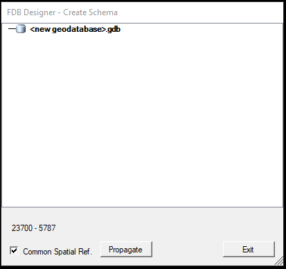
To start the design, right-click on the white area and select the Create Geodatabase Schema option. The new geodatabase will appear in the design without feature datasets and feature classes.
Right-clicking on the new geodatabase will display the following options:
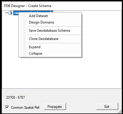
Add Dataset - Add a new Feature Dataset to the database
Design Domains - Design domains for the attributes. This functionality is currently under review.
Save Geodatabase Schema - Save the database to a folder. Please note that the target folder name shall contain the .gdb extension at the end; otherwise, the software cannot save it. If an existing geodatabase is being modified, the originally opened geodatabase cannot be overwritten; a new folder shall be specified.
Close Geodatabase - Close the currently opened geodatabase. The software will prompt the user if they want to close the database. Not saved changes will not be stored.
Expand/Collapse - Expand/Collapse the tree structure.
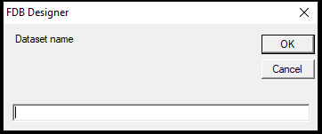
The next step in the design is to add a Feature Dataset by using the Add Dataset option. The software will prompt the user to specify the dataset name.
After pressing OK, the dataset will appear in the tree structure. Right-clicking on the freshly created feature dataset will display the following options:
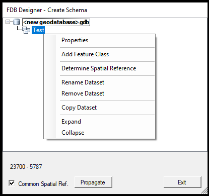
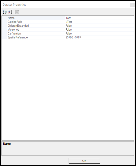
Properties - Properties of the Feature Dataset. The user cannot change anything here.
Add Feature Class - Add a Feature Class to the Feature Dataset. The new feature class will be created as a point table, but it can be changed after the creation.
Determine Spatial Reference - If the Spatial Reference is not set at the beginning of a separate projection shall be set, it can be done here using the above-described windows.
Rename Dataset - Rename the selected Feature Dataset.
Remove Dataset - Remove the selected Feature Dataset.
Copy Dataset - Copy the currently selected Feature Dataset. The copy function will copy the projection from the source dataset, but the user can assign a new name to the dataset. Feature Classes will not be copied.
Expand/Collapse - Expand/Collapse the tree structure.
The user can add Feature Classes to the created Feature Dataset. As described above, the freshly created Feature Class will have a point geometry type, which can be changed upon right-clicking the created Feature Class. After creating a Feature Class, the following options are available:
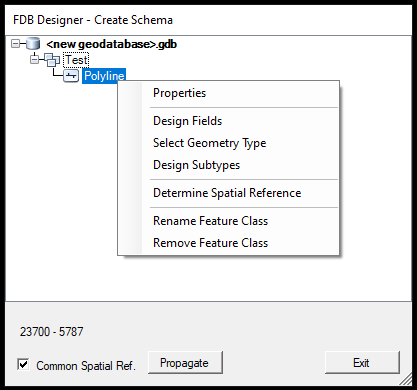
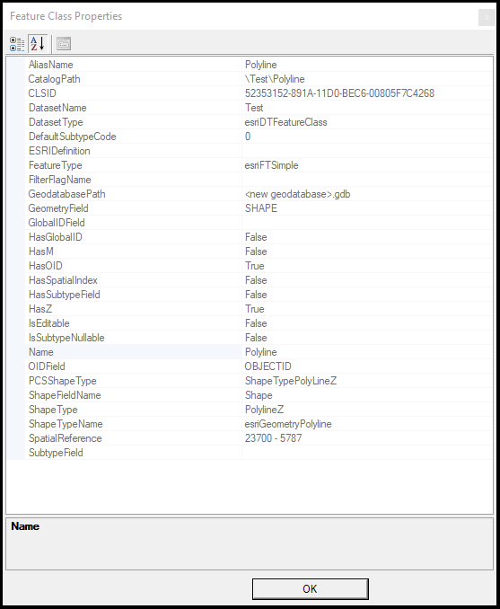
Properties - Properties of the Feature Class. The user cannot change anything here.
Design Fields - The user can design the attributes for this table here. See the detailed description below.
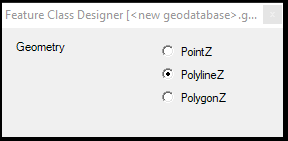
Select Geometry Type - Select the Feature Class geometry type.
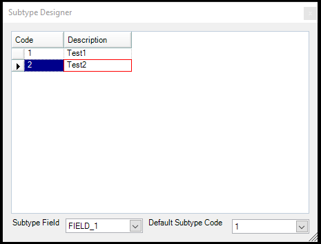
Design Subtypes - Subtypes - from a PCS aspect - are considered the counterpart of the SHP templates. If the user creates the fields, the subtypes can be specified for the created fields and serve as pre-set attributes. This functionality has some similarities with the domains. The function is still in the development phase.
Determine Spatial Reference - If the Spatial Reference is not set at the beginning of a separate projection shall be set, it can be done here using the above-described windows.
Rename Feature Class - Rename the selected Feature Class.
Remove Feature Class - Remove the selected Feature Class.
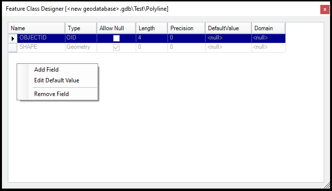
The attribute (field) design is the next step if the geometry is set for the feature class. Selecting the Design Fields option will open the field designer, where the new fields (attributes) can be appended. Right-clicking in the empty area will allow the user to create, rename and remove the attributes (which are created by the user). The object ID and the geometry are non-removable fields from the table.
The field type can be a date, double, integer, single, small integer, and string.
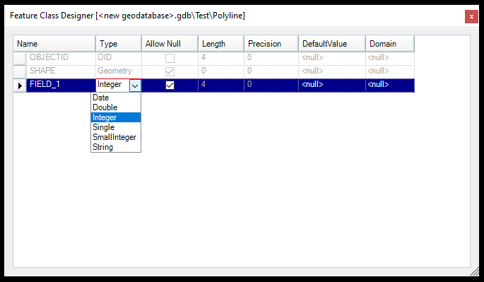
The user can adjust the length, the precision (if applicable) and the field's default value. The domains for the field can also be assigned here - design as many fields as needed.
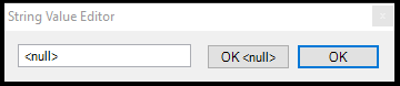
If it is needed, the user can also design the subtypes. The subtypes that will appear in the Template are of the attribute table during the extraction in PCS. The user can assign the subtypes to fields and select a default value. The respective attributes will be filled when an object is extracted using a subtype.
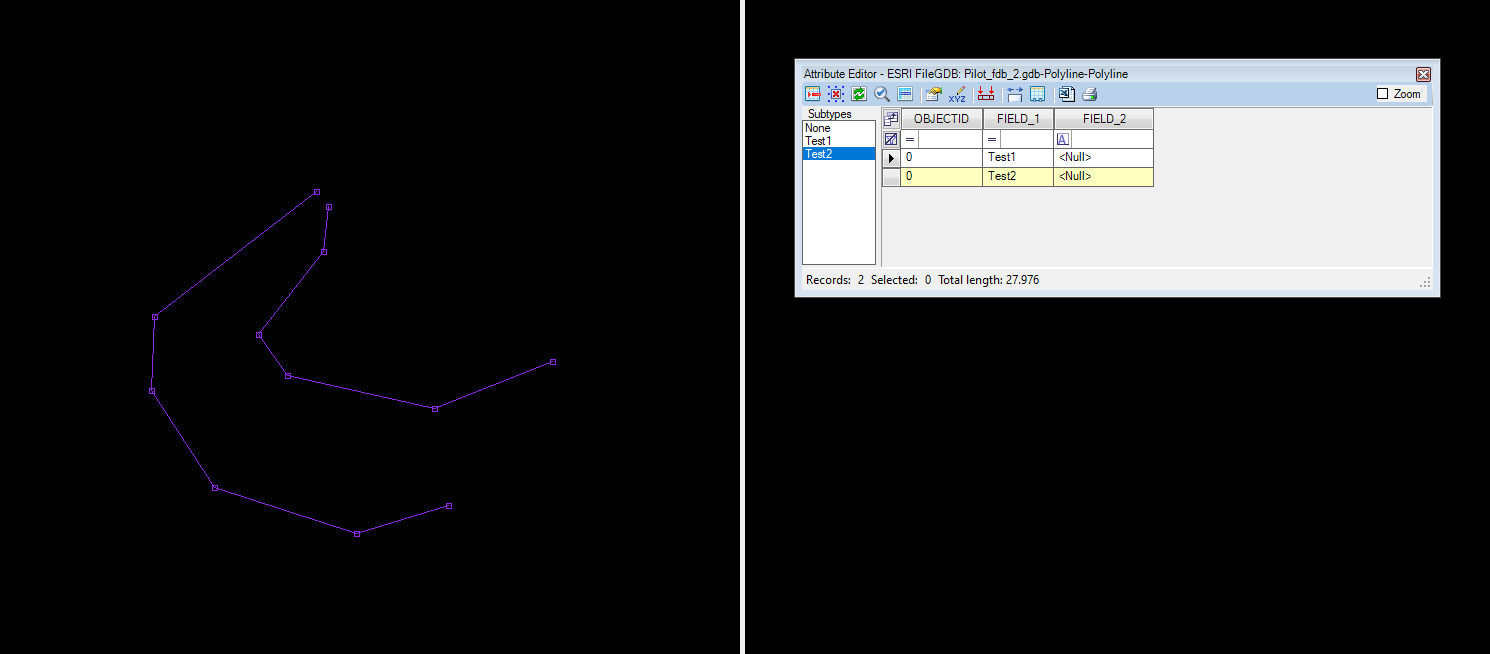
When the design is completed, right-click on the database and select Save Geodatabase Schema. Do not forget to select a target folder with the .gdb extension in the folder name. After creating the database, the user can open it and use it for extraction from the Project Explorer - Vectors level.
If the file geodatabase is used for CAD-based extractions, all CAD attributes shall exist in the geodatabase, as it is not possible to quickly append those as they are available for the SHP files. Please refer to the respective guide.