¶ Project Explorer
The project explorer is the main overview window for the software where the user can load and browse data which has been loaded into the project. The project explorer stores the information in a tree structure, where the data is categorised into Rasters, Clouds, Vectors, Trajectories, Geophotos and Camera calibrations. To interact with each group, right-click over the respective group. The Project Explorer is a dockable window that is docked to the Main Window by default.
The user can turn the groups or discrete layers on and off by unchecking the checkbox before the selected layer or layer group. At the top level, the project name can be seen. The default name is Project-1. After the user saves the project, the name will be modified to the saved file name.
¶ Project
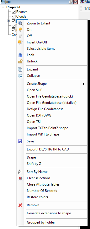
The project name can be found at the top of the tree, which is - by default - Project-1. The user can reach some functions by right-clicking this line.
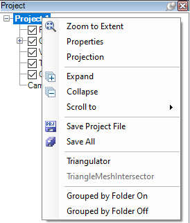
The definition of the tools are the following:
Zoom to Extent - Zooms to the extent of all content in the project. If the project contains various projection data or data with a more considerable distance, some garbage at 0,0,0 coordinate, the zoom to the extent most probably gives you back a blank screen. If this happens, zooming into each layer to determine which data package is projected incorrectly is recommended.
Properties - Properties of the project for developer use. This function is not described as it has no use for the user, and the functions can also be accessed from other locations.
Projection - The projection setting allows the user to set the projection for the project. This setting MUST BE SET to use the Google Maps Window. Upon selecting the option, the projection panel will appear.
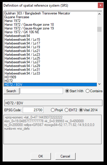
The default projection is HD72/EOV - EPSG:23700. From each projection, multiple included. The image above shows that HD72 has various versions, so using the exact EPSG code is recommended. For an overview of the EPSG code system, please read this article. Users can search by name or enter the EPSG code in the respective field. After entering the information, press enter and click on another field, as the result might not appear instantly.
The user needs to set the correct projection to be able to use the Google Maps Window, as it will project the data's coordinates to WGS84 to match the Google Maps system, and the software cannot provide the user with an accurate location if the input projection has not been set.
After setting the projection, press OK, and it will be applied during the project. Please note that this projection setting will not modify the projection of the LAS files (if the projection is coded to the header) or vector files (SHP file's .prj file also cannot be created or modified). This projection setting is applied only within the PCS environment.
Expand/Collapse - Expand or Collapse the whole project manager tree structure.
Scroll to - Select the data group to which the view should be scrolled. This can be useful if hundreds or thousands of files are imported into the project.
Save Project File - Save ONLY the project file. Please read more about saving by clicking here.
Save All - Save the project file and all vector files (and LAS files if applicable).
Triangulator - Start the triangulator functions from this page. Read the full description of the tool by clicking here.
TriangulatorMeshIntersector - Currently unavailable function.
Grouped by Folder On/Off - Group all data by folder on and off. By default, the loaded files appear with a complete file path. If the Group by folder option is turned on here (or for any data groups), the tree structure will display the folders, and inside the folders, the user can see each file with their filename.
¶ Rasters
The raster group can be used for various georeferenced images. Right-click on the "Rasters" to open the menu, where the user can interact with the rasters. Some functions become active only when a minimum of one raster is opened.
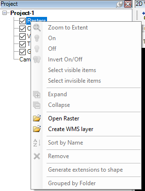
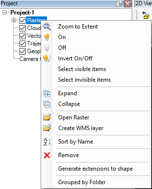
The definition of the tools are the following:
Zoom to Extent - Zoom to the extent of all loaded raster files.
On - Turn on the selected raster(s)
Off - Turn off the selected raster(s)
Invert On/Off - Invert the on/off settings for the rasters
Select Visible Items - Select visible (turned on) rasters in the project tree
Select Invisible Items - Select invisible (turned off) rasters in the project tree
Expand - Expand the project tree for rasters
Collapse - Collapse the project tree for rasters
Open Raster - Open a raster to be loaded into the project. The user can drag and drop the files directly to one of the views or the project explorer. By default, the drag-and-dropped files will be turned off.
Create WMS layer - Create a WMS layer using an access point and credentials.
Sort by Name - Sort the loaded files in alphabetic order
Remove - Remove the selected raster(s) from the project
Generate extension to shape - This function will allow the users to extract the tile extents for all rasters into a new polygon SHP file. The generated SHP file will have the tile name and file path as attributes.
Group by folder - Group the loaded rasters by containing folder
After a minimum of one file is loaded, the user can right-click the selected file(s) and reach the file-related functions.
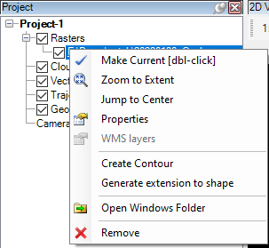
The definition of the tools are the following:
Make Current - Make the selected file active.
Zoom to Extent - Zoom to the extent of the selected raster file(s).
Jump to Center - Jump to the centre of the selected object. This function can be used only with a single layer. The scale factor will not be modified.
Properties - Properties of the selected file(s). This function can be used with a single layer; in some cases, multiple selections are also accepted.
WMS Layers - Open the WMS layer settings. Available only if the selected layer is a WMS layer.
Create Contour - Create contours based on the raster DTM surface.
Generate extension to shape - This function will allow the users to extract the tile extent for the selected raster(s) into a new polygon SHP file. The generated SHP file will have the tile name and file path as attributes.
Open Windows Folder - Open the file location in a new Windows Explorer window.
Remove - Remove the selected raster(s) from the project
¶ Clouds
The cloud group can be used for point clouds. Right-click on the "Clouds" to open the menu, where the user can interact with the point clouds. Some functions become active only when a minimum of one cloud is opened.
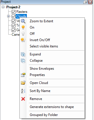
The definition of the tools are the following:
Zoom to Extent - Zoom to the extent of all loaded cloud files.
On - Turn on the selected cloud(s)
Off - Turn off the selected cloud(s)
Invert On/Off - Invert the on/off settings for the clouds
Select Visible Items - Select visible (turned on) clouds in the project tree
Select Invisible Items - Select invisible (turned off) clouds in the project tree
Expand - Expand the project tree for clouds
Collapse - Collapse the project tree for clouds
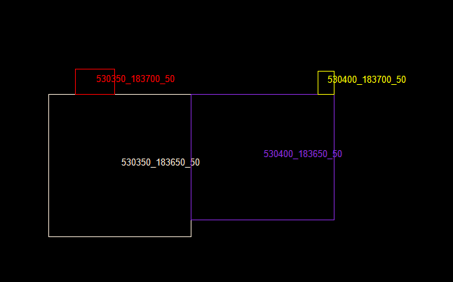
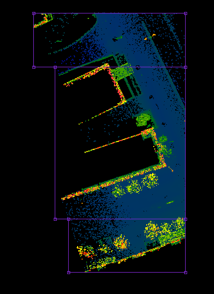
Show Envelopes - This function will show extent rectangles for each loaded LAS file with different colours and indicate the file name in the middle of the rectangle. In the Navigate Toolbar - 2D view settings panel the user can enable the function which will grey out the turned-off envelopes. The function by default is turned off, so the turned-off cloud envelopes will disappear.
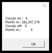
Properties - This function will show how many point cloud files are loaded and the total point number for the turned-on and off files.
Open Cloud - Open one or more LAS file(s). The user can drag and drop the files directly to one of the views or the project explorer. By default, the drag-and-dropped files will be turned off. If the default optimisation setting has been set, it will be automatically performed when the user turns on the files. If the user drops non-optimised clouds to the project, the software optimises them when turned on. The user can also open LAZ files using this function. The user cannot see the LAZ files in the browser window by default. To select the LAZ file(s), enter *.laz in the file name field and press enter. This will switch the browser window to search for LAZ files, and LAZ files can be selected. The default LAS settings won't be applied for LAZ files, so the software will not try to optimise non-optimised LAZ files. Non-optimised LAZ files will appear in 2D view above the scale of 1:50 as fragmented.
Sort by Name - Sort the loaded files in alphabetic order
Remove - Remove the selected cloud(s) from the project
Generate extensions to shape - This function will allow the users to extract the tile extents for all clouds into a new polygon SHP file. The generated SHP file will have the tile name and file path as attributes.
Group by folder - Group the loaded clouds by containing folder
After loading at least one file, the user can right-click the selected file(s) and reach the file-related functions.
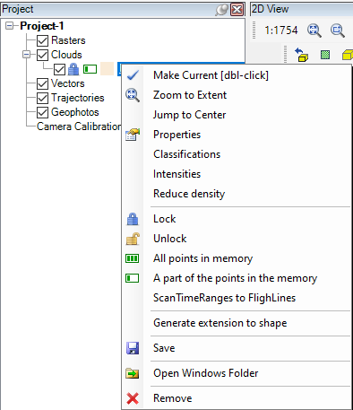
The definition of the tools are the following:
Make Current - Make the selected file active.
Zoom to Extent - Zoom to the extent of the selected cloud file(s).
Jump to Center - Jump to the centre of the selected object. This function can be used only with a single layer. The scale factor will not be modified.
Properties - Properties of the selected file(s). This function can be used with a single layer; in some cases, multiple selections are also accepted.
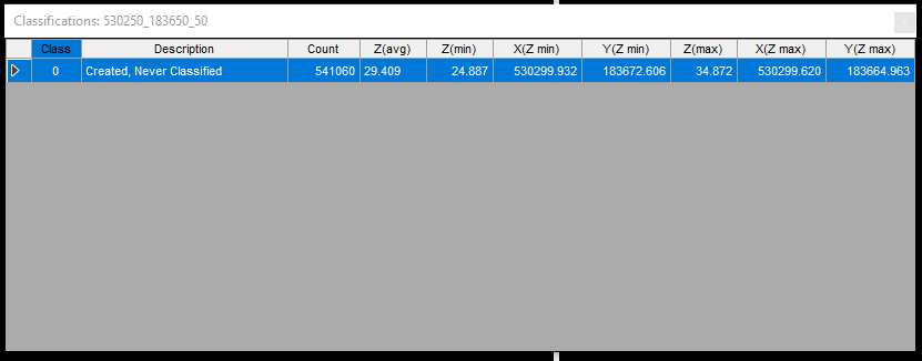
Classifications - This function will analyse the selected file and provide statistics about the used classes. It can be used only with a single LAS file. Please note that the progress may take a while.
Intensities - This function will analyse the selected file and provide statistics about the intensities to the console. It can be used only with a single LAS file. The progress may take a while, and the result can be seen in a pop-up window.
Reduce Density - This function allows the user to reduce the density of a point cloud. A detailed explanation of the function can be read here.
Lock - Lock unlocked elements so these cannot be modified. For all clouds loaded using part of the points in memory option, this setting cannot be changed and set to permanent lock.
Unlock - Unlock locked elements so these can be modified. Loading all cloud points into the memory automatically unlocks the cloud.
All points in memory - This setting will load all points of the point cloud to the memory and enable the classification tools. Please note that it is impossible to load more GB of LAS files to the memory than physical RAM can be found in the PC (for example, if the user wants to load 40 GB of LAS, but only 32 GB of RAM is installed in the PC, the software will crash. It is also recommended not to cover physical RAM fully with point clouds as PCS would occupy most of the RAM, and the system would get sluggish).
A part of the points in the memory - This is the default setting, and in standard cases, it is recommended to keep it as default. That way, the software will load only as many points as it needs. Classification tools are unavailable if this setting is being used.
ScanTimeRanges to Flightlines - This function allows the user to overwrite the Flightline attribute of the points with the given scan time ranges. - Currently unavailable function.
Generate extension to shape - This function will allow the users to extract the tile extent for the selected cloud(s) into a new polygon SHP file. The generated SHP file will have the tile name and file path as attributes.
Save - Save the selected element(s).
Open Windows Folder - Open the file location in a new Windows Explorer window.
Remove - Remove the selected cloud(s) from the project.
In the project explorer, a little lock, a battery icon and a colour rectangle can be seen for each point cloud element. If the lock is locked the file cannot be modified, if unlocked, it can be modified. The battery icon refers to the amount of points loaded into the software. A full battery represents that all points are loaded into the memory; in this case, the lock is unlocked. If only one bar is presented in the battery icon, it means that only part of the points are loaded to the memory, and the lock remains closed as a cloud can be modified only if all points are loaded to the memory. The colour rectangle refers to the default colour of the cloud. The default colour can be used to visualise different cloud files with various colours, for example, when the user wants to compare different records or station data against each other. The default colour can be modified:
- For a single LAS file, right-click on it, select Properties, and change the default colour at the top of the properties panel.
- For multiple LAS files, select the files, right-click on them, and select the Default Colour option.
- For a whole folder, right-click on the folder and select the Default Colour option. The user can select a folder only when the Group by Folder option is selected.
¶ Vectors
The vector group can be used for various vector files. Right-click on the "Vectors" to open the menu, where the user can interact with the vectors. Some functions become active only when a minimum of one vector is opened.
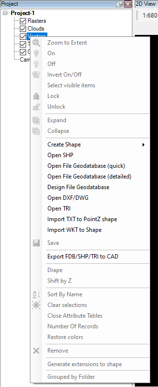
The definition of the tools are the following:
Zoom to Extent - Zoom to the extent of all loaded vector files.
On - Turn on the selected vector(s)
Off - Turn off the selected vector(s)
Invert On/Off - Invert the on/off settings for the vectors
Select Visible Items - Select visible (turned on) vectors in the project tree
Expand - Expand the project tree for vectors
Collapse - Collapse the project tree for vectors
Create Shape - Create an empty Point/Polyline/Polygon shape file. The created SHP file will never have a set projection and can store 3D coordinates. The created SHP file will contain only an incremented ID attribute; the user shall append all other attributes.
Open SHP - Open an already existing SHP file of any type. If the SHP has a projection, the software will ignore it. PCS will automatically recognise the geometry type. PCS has no limit on SHP record numbers. Still, as other software might experience difficulties opening an SHP with thousands of records, PCS might also get slower using enormous SHP data packages. The user can drag and drop the files directly to one of the views or the project explorer. By default, the drag-and-dropped files will be turned off.
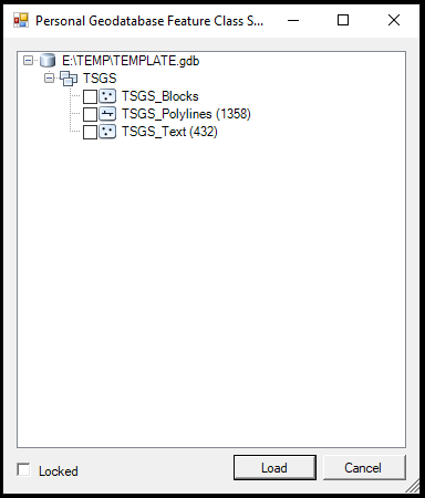
Open File Geodatabase (quick) - Open a file geodatabase without reading the items inside the tables. Select a *.gdb folder to open, and in the pop-up window, select the tables the user would like to open. In the pop-up window, the software will show which table contains what type of geometries. By checking the checkbox and pressing load, the software will load the tables, which will behave the same as an SHP file. The user cannot drag and drop FDB folders to PCS.
Open File Geodatabase (detailed) - Open a file geodatabase by reading the items inside the tables. It might take a longer time based on the amount of data inside the database. By right-clicking the DB name, the user can select only those tables that are not empty to be loaded.
Design File Geodatabase - The users can design their empty geodatabase with this function. See a detailed explanation of the function by clicking here.
Open DXF/DWG - The user can open DXF and DWG files using this function up to the ACAD 2013 version. Nothing will happen if the user tries to load a DXF/DWG file newer than the supported date (2013). The user can drag and drop the files directly to one of the views or the project explorer. By default, the drag-and-dropped files will be turned off.
Open TRI - The user can open triangulated TRI files to the project created previously by PCS. Read the triangulator page for more info. The user cannot drag and drop TRI files to PCS.
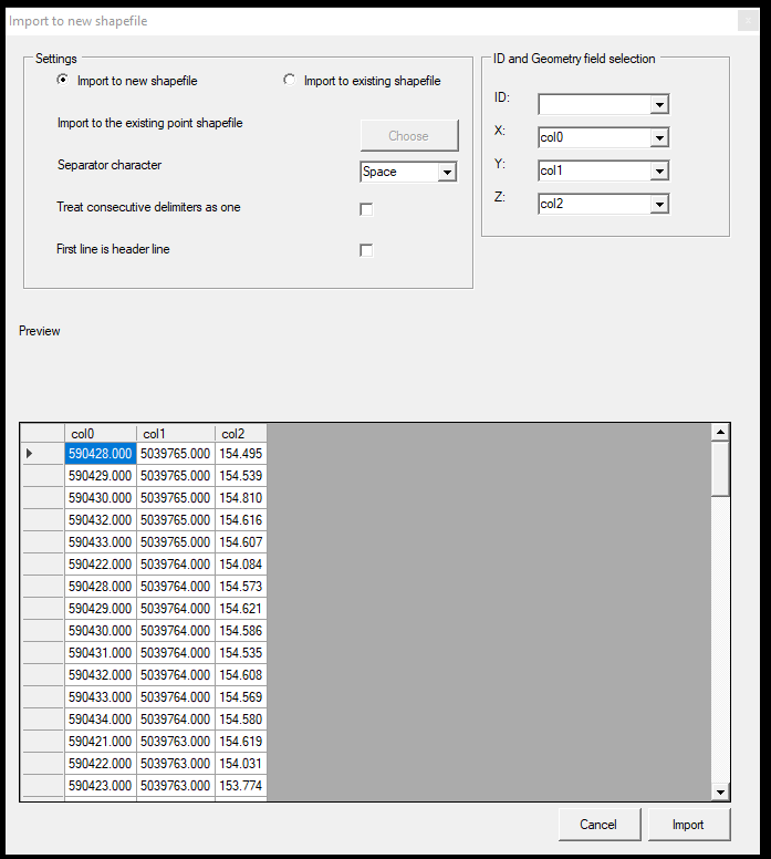
Import TXT to PointZ shape - The function will ask the user to select a TXT or CSV file. This file can have a header, but it's not necessary. It shall contain coordinates in columns, separated by a character. After opening the file, the software will show the user how the file is understood. The user may adjust the header, separator character, and the XYZ coordinate columns. The user can import the file to an existing shape, but by best practice, importing them to a new point SHP is recommended. The SHP file will be created with the ID attribute.
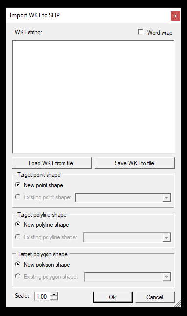
Import WKT to SHP - Import a WKT Text to SHP file. After starting the tool, the import dialogue will appear, where the WKT string can be appended, loaded from a file, saved to a file, and the SHP properties and target files can be set.
Save - Save the selected group of vectors. Depending on the selection, the user can save all vectors, one vector or selected vectors.
Export FDB/SHP to DXF - This function allows the user to export from SHP and FDB to DXF/DWG formats. This function is available only at the Vectors level of the project manager; the user cannot see this option by right-clicking on a single SHP file. The export has a set of criteria that the used SHP/FDB files shall meet. A detailed explanation can be read on the Extraction to CAD environment page.
Drape - Drape all vectors to the point cloud(s). This applies only to SHP and FDB files. For a detailed explanation of the drape in general, check this page.
Shift by Z - The user can use this function to shift the active, visible or all SHP geometries (or selected elements) with a single Z value.
Sort by Name - Sort the files by filename.
Clear selection - Clear all selection for all vector layers.
Close attribute tables - Close all opened attribute table windows.
Number of Records - Checks the total number of records inside all vector files. The result will be displayed in a new window.
Restore Colors - Reset the vector display colour for all SHP and FDB tables to the default value. The function does not affect the CadColor attribute. Those vectors which are coloured by the CadColour attributes will keep the colouring.
Remove - Remove all vectors from the project.
Generate extensions to shape - This function will allow the users to generate tiles around the extent of the vector layers into a new polygon SHP file. The generated SHP file will have the tile name and file path as attributes.
Group by folder - Group the loaded vectors by containing folder
After loading vector data, the right-click menu varies according to the selected vector type.
- For SHP files (Point, Polyline, Polygon):
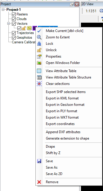
Make Current - Make the selected file active.
Zoom to Extent - Zoom to the extent of the selected vector file(s).
Lock - Lock the layer. The geometry of the locked layers cannot be modified. The attributes can still be modified.
Unlock - Unlock the layer. All vector layers - where it is applicable, by default - are unlocked.
Properties - Properties of the selected file(s). This function can be used with a single layer; in some cases, multiple selections are also accepted.
Open Windows Folder - Open the file location in a new Windows Explorer window.
View Attribute Table - Open the attribute table of the selected SHP file.
View Attribute Table Structure - Inspect and modify the selected SHP file's attribute structure. This menu point is only visible upon right-clicking the active SHP; non-active SHPs will not have this option. Read more about the attribute structure modifications by clicking here.
Clear Selection - Clear all selections in the selected file(s).
Export SHP selected items - Export the selected records from the SHP file to a new SHP file. The result SHP will have the same type and attribute structure as the source SHP.
Export in KML format - Export the selected SHP to a Google KML format. This operation can only be performed if the projection has been set for the project in the explorer. Read the projection description above.
Export in Geojson format - Export the selected SHP to a Geojson format. This operation can only be performed if the projection has been set for the project in the explorer. Read the projection description above.
Export in PLY format - Export the selected SHP to a PLY format.
Export coordinates - Export the coordinates of the elements inside the SHP file to an ASCII text.
Append DXF attributes - This function supports the extraction to a CAD environment, and the primary purpose is to append the required attributes to an SHP file, which are needed during the export from PCS to a CAD environment. It can append attributes to Points (Block type, Point type, Text type), Polylines and Polygons, even if the SHP file already has attributes. For a deeper understanding of the CAD extraction, please read the extraction to CAD environment page.
Generate extensions to shape - This function will allow the users to generate tiles around the extent of the selected vector layer(s) into a new polygon SHP file. The generated SHP file will have the tile name and file path as attributes.
Drape - Drape the selected vector to the point cloud(s). For a detailed explanation of the drape in general, check this page.
Shift by Z - The user can use this function to shift the geometries within the selected SHP(or only the selected elements) with a single Z value.
Save - Save the selected vector(s).
Save As - Save the selected SHP file to a new name.
Save As 2D - Save the current SHP file to a new SHP, where all Z values are set to 0.
Remove - Remove the selected SHP(s).
- For File Geodatabases (FDB) at the main level:
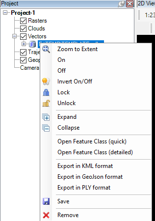
Zoom to Extent - Zoom to the extent of the whole database.
On - Turn all FDB tables on.
Off - Turn all FDB tables off.
Invert On/Off - Invert the on/off setting for all tables.
Lock - Lock the layer. The geometry of the locked layers cannot be modified, but the attributes can still be modified.
Unlock - Unlock the layer. All vector layers - where it is applicable, by default - are unlocked.
Expand - Expand the FDB tree structure.
Collapse - Collapse the FDB tree structure.
Open Feature Class (quick) - Open a file geodatabase without reading the items inside the tables. In the pop-up window, the software will show which table contains what type of geometries. By checking the checkbox and pressing load, the software will load the tables, which will behave the same as an SHP file. This function allows the opening of additional tables not opened when the FDB was first loaded into the project. Already opened tables will be checked.
Open File Geodatabase (detailed) - Open a file geodatabase by reading the items inside the tables. It might take a longer time based on the amount of data inside the database. By right-clicking the DB name, you can select only those tables that are not empty to be loaded. This function allows the opening of additional tables not opened when the FDB for the project was first loaded. Already opened tables will be checked.
Export in KML format - Export the complete FDB to a Google KML format. This operation can only be performed if the projection has been set for the project in the explorer. Read the projection description above.
Export in Geojson format - Export the complete FDB to a Geojson format. This operation can only be performed if the projection has been set for the project in the explorer. Read the projection description above.
Export in PLY format - Export the complete FDB to a PLY format.
Save - Save the complete FDB; all tables will be saved.
Remove - Remove the whole FDB from the project.
- For tables inside the file geodatabase:
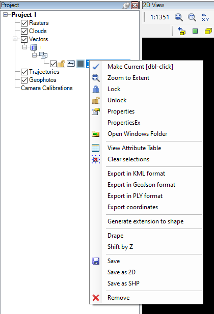
Make Current - Make the selected table active.
Zoom to Extent - Zoom to the extent of the database table.
Lock - Lock the layer. The geometry of the locked layers cannot be modified, but the attributes can still be modified.
Unlock - Unlock the layer. All vector layers - where it is applicable, by default - are unlocked.
Properties/PropertiesEx - Properties of the selected database table and the extended properties.
Open Windows Folder - Open the file location in a new Windows Explorer window.
View Attribute Table - Open the attribute table of the selected database table.
Clear Selection - Clear all selected database table(s) selections.
Export in KML format - Export the selected FDB table to a Google KML format. This operation can only be performed if the projection has been set for the project in the explorer. Read the projection description above.
Export in Geojson format - Export the selected FDB table to a Geojson format. This operation can only be performed if the projection has been set for the project in the explorer. Read the projection description above.
Export in PLY format - Export the selected FDB table to a PLY format.
Export coordinates - Export the coordinates from the active FDB table to a CSV file.
Generate extensions to shape - This function will allow the users to generate tiles around the extent of the selected FDB table(s) into a new polygon SHP file. The generated SHP file will have the tile name and file path as attributes.
Drape - Drape the selected database table to the point cloud(s). For a detailed explanation of the drape in general, check this page.
Shift by Z - The user can use this function to shift the geometries within the selected FDB table(or only the selected elements) with a single Z value.
Save - Save the selected FDB table.
Save As 2D - Save the current database table to a new SHP, where all Z values are set to 0.
Save As SHP - Save the current FDB table as an SHP file. The exported SHP file will have the same geometry type as the source table and contain all attributes. The SHP file is not loaded into the project automatically.
Remove - Remove the selected FDB table from the project.
- For DXF/DWG files:
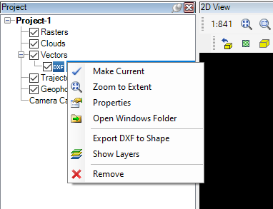
Make Current - Make the selected file active.
Zoom to Extent - Zoom to the extent of the selected vector file(s).
Properties - Properties of the selected file(s).
Open Windows Folder - Open the file location in a new Windows Explorer window.
Export DXF to SHP - This function allows users to convert DXF/DWG files to SHP format. PCS will split the DXF/DWG file into texts, blocks, points, and polylines and create the SHP files with the respective CAD attributes. Please check the Extraction for CAD Environments guide for a detailed explanation of the tool.
Show Layers - Open the layers dialogue, where the user can turn on and off layer visibility or change colour for a layer.
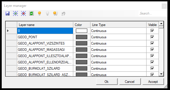
The tools in the layer manager are the following:
- Save - Save the ACCEPTED changes to the active DXF/DWG file. If the changes are not accepted, the software will prompt the user, if the changes will be applied or not.
- Select all layers
- Deselect all layers
- Invert selection
- Set All Visible - Turn all layers on
- Set All Invisible - Turn all layers off
- Invert visibility
- Undo changes - Undo all changes that has not been accepted yet.
Remove - Remove the selected DXF(s)/DWG(s) from the project.
- For TRI files:
Zoom to Extent - Zoom to the extent of the triangulated surface.
Properties - Properties of the triangulated surface. The user can modify the colour of the triangle lines if the surface triangles are filled and which fill colour shall be used. Some basic information can be accessed here, like the number of triangles, average edge length, and XY extent coordinates.
Export in PLY format - Export the triangulated surface to a PLY format for further use.
Export in Shape format - Export the triangles to a polygon shape format. Please note that a more extensive area might contain too many triangles, which might be too heavy for an SHP file. We recommend using this function for smaller files, up to a few thousand triangles.
Export in DXF/DWG format - Export the surface as 3D faces to a DXF or DWG file format. This export does not require any attribute settings for the DWG (as the triangulated file has no attribute).
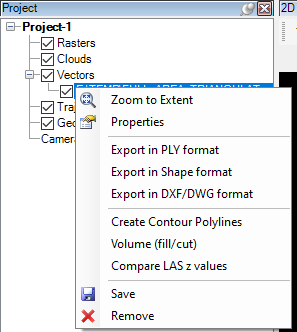
Create Contour Polylines - This function will create contours from the surface based on the user parameters. See the settings below. Also, check the Surface and Contour generation guide to understand the usage better.
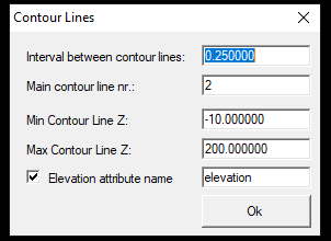
Using the contour settings, the user can set the step level and the elevation range between the contours that need to be generated. The created contour file will be a polyline SHP, and the user can include the elevation value as an attribute. If the user wants to export the contours to a DXF/DWG file, use the append DXF attributes from the project manager to this SHP file and assign the proper attributes.
Volume Cut/Fill - This function allows the user to specify an elevation, and the software will create an XY plane at this elevation and intersect the surface with this plane to provide the cut and fill values. This function can be used for depo calculation.
Compare LAS Z values - This function allows users to compare the surface against the point cloud. Please find the detailed description of this tool by clicking here.
Save - Save the TRI file at the designated location.
Remove - Remove the triangulated surface from the project.
¶ Trajectories
Trajectories are rarely used objects. Currently, PCS supports only a specific structured trajectory in TXT format. This format can be directly exported from RiProcess but might be reached using other post-processing software. It may be possible that the user creates the format manually from the raw/different datasets that their mobile system provides. Please read this article to understand the supported trajectory format better.
Trajectories are separate from vectors, but PCS displays them as a polyline, where each trajectory point is a vertex on a polyline. Right-click on the "Trajectories" to open the menu, where users can interact with the trajectories. Some functions become active only when a minimum of one trajectory is opened.
The definition of the tools are the following:
Zoom to Extent - Zoom to the extent of all trajectories.
On - Turn all trajectories on.
Off - Turn all trajectories off.
Invert On/Off - Invert the on/off setting for all trajectories.
Select visible items - Select the visible (non-turned-off) trajectories in the project explorer tree structure.
Expand - Expand the trajectories tree structure.
Collapse - Collapse the trajectories tree structure.
Open Trajectory - Open a trajectory file.
Save - Save the modifications of the trajectory.
Remove - Remove the trajectories from the project.
Group by folder - Group the loaded trajectories by the containing folder.
After loading the trajectory data, the following tools are available at the right-click menu:
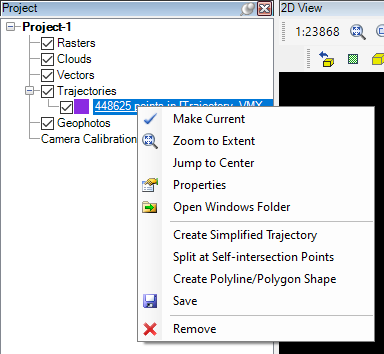
Make Current - Make the selected file active.
Zoom to Extent - Zoom to the extent of the whole trajectory.
Jump to Center - Jump to the centre point of the selected trajectory's extent using the current scale.
Properties - Properties of the selected file(s).
Open Windows Folder - Open the file location in a new Windows Explorer window.
Create Simplified Trajectory - Simplify the trajectory using the Ramer-Douglas-Peucker algorithm.
Split at Self-intersection Points - Create separate trajectories based on self-intersections. Please note that the software will not calculate a new point on the trajectory instead it drops the last segment of the trajectory and splits it only based on existing trajectory points.
Create Polyline/Polygon Shape - Create a Polyline or Polygon from the trajectory into the active SHP file. Please create a new SHP file and set it to active before using the function. If the trajectory contains over a few thousand points, it may result in an SHP file with too many vertices. Consider this before the use of the function.
Save - Save the current file(s).
Remove - Remove the selected file(s).
¶ Geophotos
Geophotos are images taken by the TLS/MLS (or other sensors if the special conditions are met) systems and properly georeferenced so the image's position can be restored based on the recorded parameters (position, camera position and rotation parameters, timestamps, etc.). The market leader manufacturers provide this information in the required format (Riegl, Leica, Topcon, Trimble, etc.). Still, suppose a manufacturer is capable of colouring the point cloud based on the recorded images; it means that the required information for the PCS to be able to use the images is inside the system. Still, the user might be unable to export it in the required format.
The software supports two major geophoto standards: TopoDOT IPRJ and TerraPhoto Mission files. Both standards are open and text-based; click the link for more information. PCS might be able to handle other image formats or sources. For more information, contact us!
Geophotos are visualised inside PCS by default as a red square with a small stick pointing to the camera's direction (2D view) or as a red pyramid whose base is aligned with the photo direction (3D view). The project explorer will visualise the geophotos according to the original structure (per record, per camera device, one folder, etc.). The geophotos cannot be used without camera calibrations; see the section below. Please pay attention to the coordinate systems settings; if the image coordinate system mismatches the point cloud, the visualisation will not fit.
Right-click on the "Geophotos" to open the menu, where the user can interact with the geophotos. Some functions become active only when a minimum of one geophoto is opened. Opening an IPRJ or MIS file will result in the Camera Calibrations will be loaded and assigned automatically.
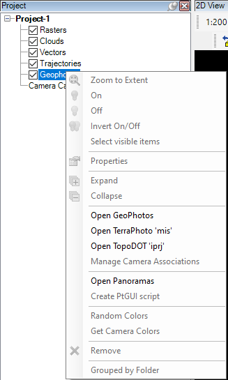
The definition of the tools are the following:
Zoom to Extent - Zoom to the extent of all loaded geophotos.
On - Turn on all geophotos
Off - Turn off all geophotos
Invert On/Off - Invert the on/off settings for the geophotos
Select Visible Items - Select visible (turned on)geophotos in the project tree
Properties - Properties of the geophotos.
Expand - Expand the geophotos tree structure.
Collapse - Collapse the geophotos tree structure.
Open Geophotos - Browse a folder where the geophotos are located. This option will allow the user to browse geophotos from folders. The folder shall contain a CSV with the image information required for PCS. We do not recommend using this function without prior instructions from the developers.
Open TerraPhoto' mis' - Open geophotos using the TerraPhoto Mission file.
Open TopoDOT 'iprj' - Open geophotos using TopoDOT IPRJ file.
Manage Camera Associations - Assign the camera devices to the camera calibrations. Using TopoDOT IPRJ or TerraPhoto Mission file will automatically assign the calibrations to the respective records.
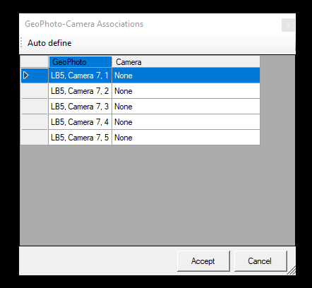
The GeoPhotos column shows the geophoto packages per camera device (based on the folder structure), and the user can assign the camera based on the opened camera calibrations.
Open Panoramas - Open panorama images using an external viewer. Currently unavailable function.
Create PtGUI script - Currently unavailable function.
Random colors - Randomise the image location marker's colour (from the default red).
Get camera colors - Currently unavailable function.
Remove - Remove all geophotos.
Group by folder - Group the loaded geophotos by the containing folder.
After loading the geophotos, the following tools are available at the right-click menu:
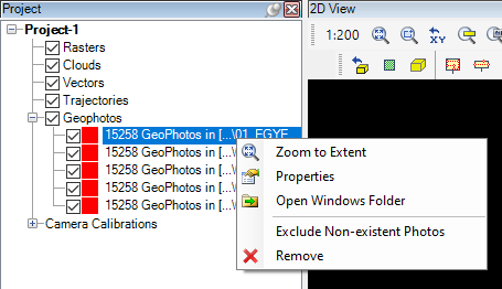
Zoom to Extent - Zoom to the extent of the selected geophoto group.
Properties - Properties of the selected geophotos.
Open Windows Folder - Open the file location in a new Windows Explorer window.
Exclude Non-existent Photos - Exclude those photo locations that have no physical photo. The location CSV might contain locations with no image in the respective place.
For a detailed description of how to use geophotos, please check the photos toolbar article.
¶ Camera calibrations
Camera calibrations are required to view the photos together with the point cloud. The geophotos CSV contains the location parameters, but the camera calibrations contain the camera parameters to project the planar images to the point cloud properly. Without camera calibrations, the projection cannot be restored. If the user opens the geophotos using TopoDOT IPRJ or TerraPhoto Mission file, the calibrations will be automatically loaded and assigned to the respective records. We do recommend to use this option, otherwise, it can be difficult manual work, if the naming is not matched through the datasets.
Right-click on the "Camera Calibrations” to open the menu, where the user can interact with the calibrations. Some functions become active only when a minimum of one calibration is opened. Opening an IPRJ or MIS file will result in the Camera Calibrations will be loaded and assigned automatically.
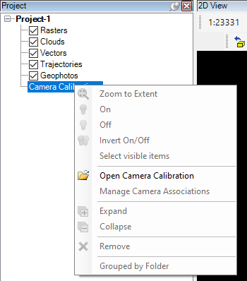
The definition of the tools are the following:
Zoom to Extent - Zoom to the extent of all loaded geophotos (which the selected calibrations are assigned to).
On - Turn on all geophotos; camera calibrations cannot be turned on or off.
Off - Turn off all geophotos; camera calibrations cannot be turned on or off.
Invert On/Off - Invert the on/off settings for the geophotos; camera calibrations cannot be turned on or off.
Select Visible Items - Select visible calibrations assigned to visible geophotos.
Open Camera Calibration - Open camera calibration .cal files.
Manage Camera Associations - Assign the camera calibration to the respective geophoto package - if it's" not assigned manually or requires any modifications.
The GeoPhotos column shows the geophoto packages per camera device (based on the folder structure), and the user can assign the camera based on the opened camera calibrations.
Expand - Expand the camera calibration tree structure.
Collapse - Collapse the camera calibration tree structure.
Remove - Remove all camera calibrations.
Group by folder - Group the loaded camera calibrations by the containing folder.
After loading the camera calibrations, the following tools are available at the right-click menu:

Zoom to Extent - Zoom to the extent of all loaded geophotos (which the selected calibrations are assigned to).
On - Turn on all geophotos; camera calibrations cannot be turned on or off.
Off - Turn off all geophotos; camera calibrations cannot be turned on or off.
Invert On/Off - Invert the on/off settings for the geophotos; camera calibrations cannot be turned on or off.
Select Visible Items - Select visible calibrations assigned to visible geophotos.
Open Windows Folder - Open the file location in a new Windows Explorer window.
Color - Change the display colour for the geophotos assigned to this camera device.
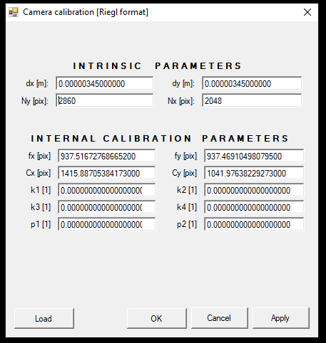
Edit - Edit the camera calibration parameters. The user can modify the camera parameters if needed. It is highly recommended that the file be backed up. Changing this setting is only recommended for highly experienced users.
Geophotos Visible - Turn on all geophotos assigned to this calibration.
Geophotos Invisible - Turn off all geophotos assigned to this calibration.
Remove - Remove the selected camera calibration(s).