¶ Topology Tools
The Topology Tools has been introduced with the Shape Layout Version 1 in the Q3-Q4 of 2023. The tools were available before under the Shape Toolbar - Topology tools dropdown menu, but in the new layout version, the tools received icons and were separated into a new toolbar. The Topology Tools is located in the Main Window. The tools are available if at least one SHP/FDB table is opened in the project; otherwise, they are greyed out.

The description of the tools are the following:
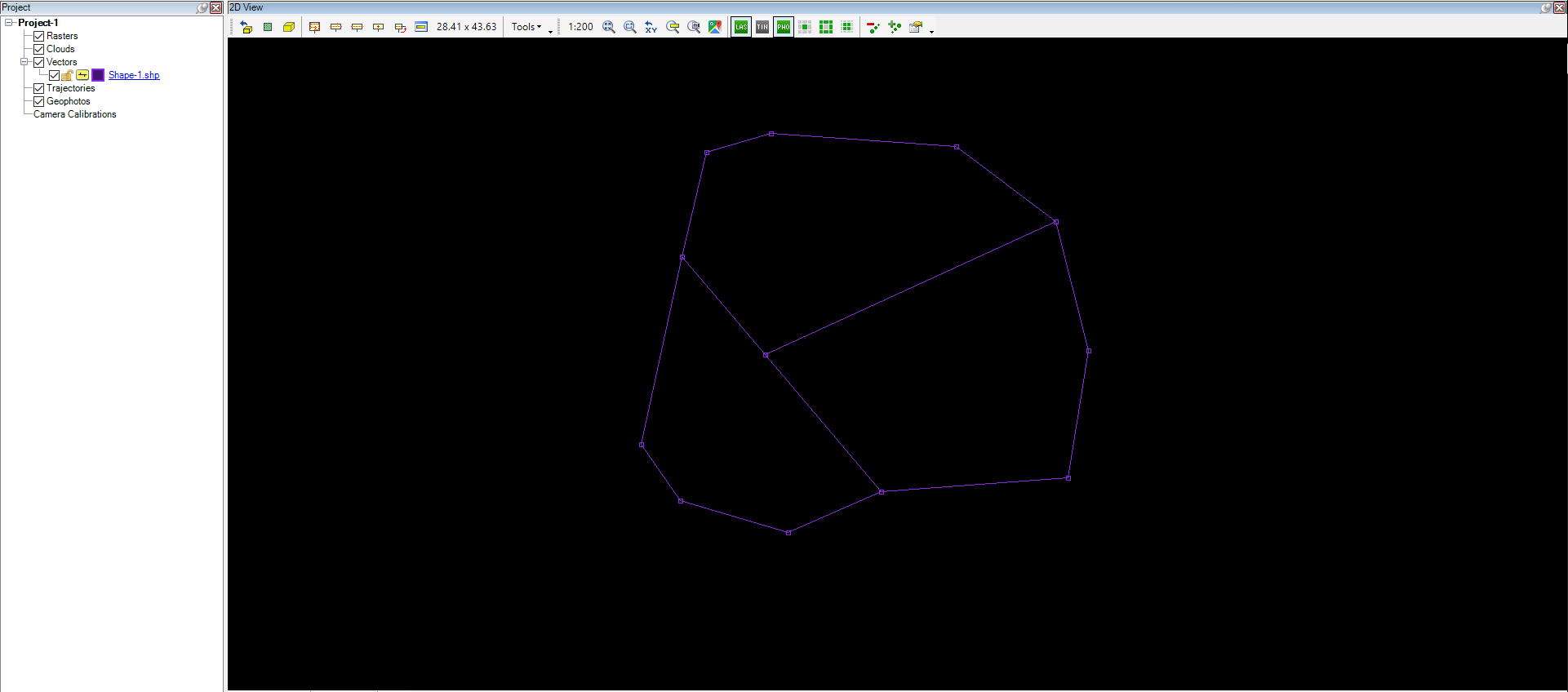
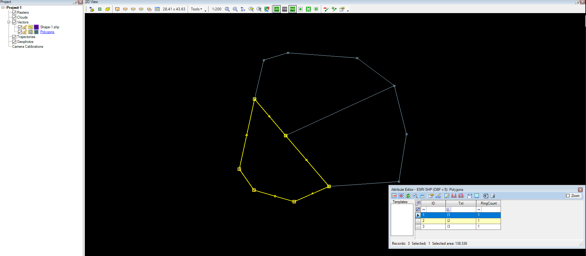
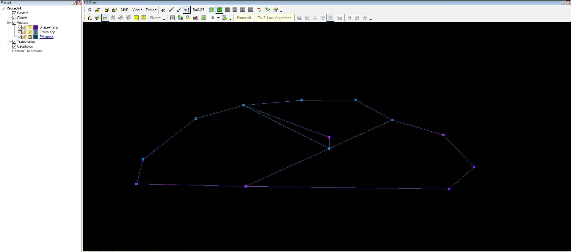
- Build Polygons - The build polygons tool generates polygons for topologically correct (no discontinued endpoints, no 2D segment intersection) linework. The tool will create a new polygon SHP where each 2D area will receive a 3D polygon. The created polygons will have ID, Txt and RingCount fields. If the linework is unsuitable for building polygons, the software will generate error point SHP file(s), which show the user where and what type of error can be found. The software will try to build polygons from all visible polyline SHP, so if the drawing contains linework, which might contain topological errors, turn them off, remove them from the project or resolve the topological errors.

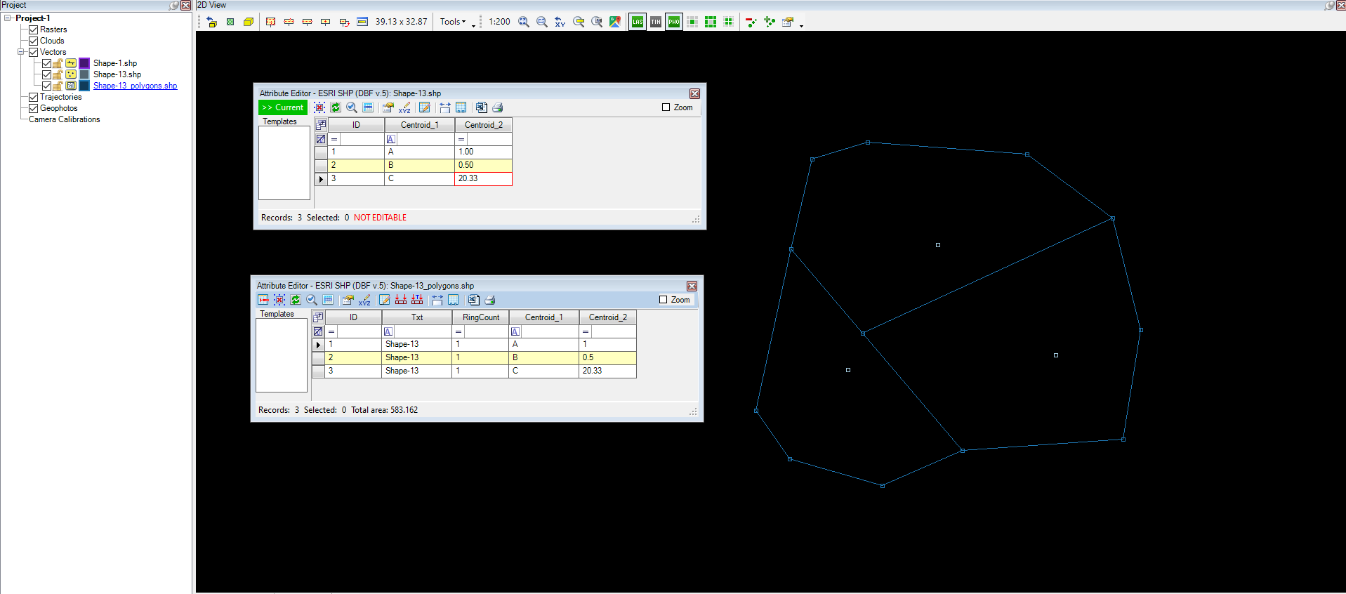
- Build Polygons (centroid mode) - This function works the same as standard Build Polygons, with the difference that each topologically correct area shall contain an ID point - a centroid - which specifies the area's attributes. The generated polygon SHP file will inherit the centroid SHP's name, and all polygons will receive - above the ID, Txt, and RingCount attributes - the centroid point's attributes. In that way, the user can use the ID point to automatically assign properties to the polygons. The centroid SHP shall be the active SHP when the tool is started.
- Average coordinates - This tool allows the users to average close coordinates for points near each other. This tool helps to eliminate minor snap errors between vertexes. After starting the tool, it prompts the user if the effect shall be applied to the active, visible or all SHP files. After selecting the affected SHPs, the software will prompt the user how many decimal places shall be averaged; the default value is 3 (will round to mm dimension; it is the recommended setting). After setting the decimal places, the software prompts the tolerance in meter dimensions; the default value is 0.01 (1 cm). This means that the software will inspect all vertexes, and if two vertexes are within 1 cm of each other and the coordinates are different up to mm dimension, those vertexes will be averaged.
- Find Discontinued Endpoints - This tool allows the users to mark all discontinued endpoints (which have no connection to any other polyline/polygon elements). This tool can be used to check the drawing before building the polygon. The tool will create a new point SHP where the endpoints will be marked with a point. The tool offers a tolerance setting with a default value of 0.000, which will accept only connections. Still, if the value is raised, small misalignments with vertexes are accepted, but those are still considered errors for polygon building. The tool can be run for the active, visible and all SHPs. If no discontinued endpoints can be found in the drawing (or in the SHPs selected as target), the software will prompt the user to say OK, indicating that the lineworks are correct. It is strongly recommended that this tool be used before building polygons.
- Find 2D segment intersections - This tool allows the users to mark all intersections without a common vertex. This tool can be used to check the drawing before building the polygons. The tool will create a new point SHP where the intersections will be marked with a point. The tool can be run for the active, visible and all SHPs. If no invalid intersections can be found in the drawing (or in the SHPs selected as target) the software will prompt OK to the user, indicating that all is good. It is strongly recommended that this tool be used before building polygons.
- Round XYZ in Geometry - This tool allows users to round all vertex coordinates to the set amount of decimals. This can help eliminate minor coordinate rounding errors that might cause CAD environment issues. After starting the tool, the software will prompt the decimal setting. The default setting is three decimals (round to mm). The tool can be run for the active, visible and all SHPs.
- Remove near points in geometry - This tool allows the users to remove near points in geometry in polyline and polygon elements. The points can be removed within the set tolerance, considering that the linework shall not change. This tool removes only the unnecessary points from the linework. The tool can be run for the active, visible and all SHPs. The point SHPs will not be modified. After starting the tool the following settings panel will appear:
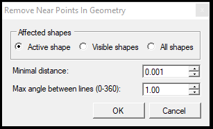
The user can set the target for the remove near points in geometry: active, visible, or all shapes, and put the minimum distance and angle tolerance (if the angle is smaller than the set value, the near point will be removed, as the geometry will change within the tolerance). The function does not apply to point SHPs, check the Remove Duplicate Points function below.
- Endpoint snapping in SHP - This tool allows users to snap close endpoints that are not snapped together based on the set tolerance. The tool can be run for the active, visible and all SHPs and only for polyline geometries.
- Build Polygons Manually - This tool allows users to build polygons manually by clicking into an area, and the area will receive a new polygon element into a new polygon SHP using the existing linework. The active SHP shall be a polygon SHP to be able to use the tool. Nothing will happen if the user clicks on an invalid location where the topology is incorrect.
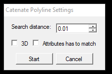
- Catenate Polylines - The function will join all touching polylines in the same SHP in 2D. The user can set a search distance within which the tool will join the polylines, even if they are not touching. The 3D checkbox allows the user to consider the elevation, and the Attributes have to match option will consider all attributes (excluding increment ID). In that way, if both checkboxes are checked, the tool will merge all polylines of the same kind if they are touched. If the targeted SHP file has more than 10.000 elements, the software will prompt the user if they would like to continue the operation as it may take a while.
- Divide All Shapes - The tool performs a divide by distance on the active, visible or all SHP files in the drawing. It is the same as the Divide tool from the Shape Toolbar, but it affects the whole drawing.
- Remove Duplicate Points - This function allows the users to remove the duplicate point geometry from the drawing. After starting the tool, the following settings panel will appear:
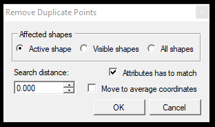
The user can set the target to remove duplicate points: active, visible, or all shapes and set the search distance for the points. The user can also set that the attributes shall be matching when the duplicate points are inspected and also there is an option to average the coordinates.