¶ Shape Toolbar
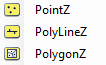
The shape toolbar is the biggest toolbar of all and the most used. The user can interact with the vector layers using this toolbar. It is named the Shape Toolbar but works the same way as File Geodatabase (FDB). The shape toolbar was refurbished during Q3 of 2023; this wiki article will focus on Shape Layout Version 1. To read more about the layout versions, please check this article. The shape toolbar icons might differ depending on the active SHP's/FDB table's geometry type. The geometry type can be point, polyline or polygon, and the icons might represent the active geometry type:
The shape toolbar becomes active only if at least one SHP or FDB table is loaded into the project; before that, all tools are greyed out.

Please note that if the user is using Layout Version 0, at the end of the SHP toolbar, there are More, Topology Tools and Tree Measure menus, which contain tools from the Shape Toolbar 2, Topology Toolbar and Advanced tools toolbar (Complex Measures Toolbar in older versions). The tools are the same, but in Layout Version 1, they have discrete icons.
The description of the tools are the following:
- Show Attribute Table - Open the currently active SHP/FDB table attribute table. For a detailed description of the attribute tables, check the respective article.
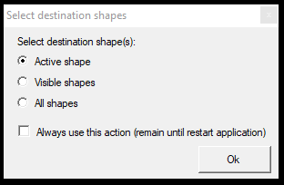
- Select Shape Item - Select SHP items visually on 2D or 3D view one by one. When the user starts the tool, it will ask if the active, visible or all-shape files shall be used. The snap mode is locked to vector snap during the use of the tool. The user can finish the command by right-clicking or pressing ESC. After closing the command, the selection remains as long as the user does not start a tool that clears the selection.
- Deselect Shape Item - Deselect SHP items visually on 2D or 3D view one by one. When the user starts the tool, it will ask if the user wants to deselect from the active, visible or all-shape files. The snap mode is locked to vector snap during the use of the tool. The user can finish the command by right-clicking or pressing ESC. The deselect command leaves the not-clicked elements as selected.
- Select Shape Items - with polygon - Select SHP items visually on 2D or 3D with a polygon. When the tool is started, it will ask if the active, visible or all-shape files shall be used. The snap mode is free point snap by default but can be changed. Start drawing a polygon for the elements that need to be selected. If a polyline/polygon element has a minimum of one vertex inside the polygon - and the SHP selection allows it - it will be selected. The polygon shall not be closed; when the user finishes drawing the polygon and presses enter, the software automatically closes the start and endpoints. After closing the command, the selection remains as long as the user does not start a tool that clears the selection.
- Unselect Shape Items - with polygon - Deselect SHP items visually on 2D or 3D with a polygon. When the tool is started, it will ask if the active, visible or all-shape files shall be used. The snap mode is free point snap by default but can be changed. Start drawing a polygon for the elements that need to be deselected. If a polyline/polygon element has a minimum of one vertex inside the polygon - and the SHP selection allows it, and the element is selected - it will be deselected. The polygon shall not be closed. When the user finishes drawing the polygon and presses enter, the software will automatically close the start and endpoints. The deselect command leaves the not-fenced elements as selected.
- Clear Shape Selection - Clear selection in SHP file(s). When the tool is started, it will ask if the active, visible or all-shape files shall be used.
- Reverse Selection - Invert the selection for the active shape - the selected records will be unselected, and the unselected records will be selected.
- Delete Selected Items - This command will remove the selected items from the attribute table. When the tool is started, it will ask if the active, visible or all-shape files shall be used. Same as Remove Item, but the user doesn't have to select the object for deletion from the views, but the selection will be used. The software will prompt whether the user wants to delete the selected items. Nothing will happen when the tool starts, and no items are selected.
- Shape Information - This tool starts with the shape info tool, which can be used to get information about SHP/FDB elements. This tool cannot be used to obtain information from point cloud points - use the Information tool located at the Measure toolbar to info point cloud points. When the tool is started, an empty info window will appear, displaying the selected element's info. The snap mode will be locked to vector snap. The information function - after selecting an element in an SHP - will reset the current selection, as the element the user requests info from will be selected. Selection will remain after the tool is closed.
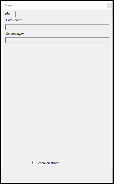
After the window appears, the user can select an element in the view. This function can select from any shape, and the active shape is irrelevant here.
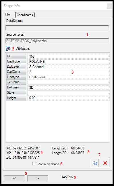
After selecting an element, the information will be presented in two tabs: info and coordinates. The Info tab provides a bunch of information divided into multiple window parts. The definitions of these functions are the following:
- The Data source and Source layer of the selected element. If the user selects an SHP element, the Data Source will be empty; if selects an FDB element, the DataSource will represent the source folder and the Source layer the table inside the FDB.
- Column selector - When the user presses this button, the user can select which columns (attributes) shall be visualised on the info page.
- Attributes - The user can see all attributes and their value for the selected element.
- The first coordinate of the element for polylines and polygons. If a point object is selected, the point coordinates are used here.
- The 2D and 3D length of the element if the selected object is a polyline. If a point object is selected, this area has no value. If a polygon object is selected, this area displays the 2D and 3D length and 2D area of the selected element.
- Zoom on shape - When an element is selected for info, the 2D view will be zoomed to the extent of the element.
- Copy Coordinates to clipboard - Remove Item buttons - When the user copies the coordinate, it will copy the first vertex's element's coordinate to the clipboard as seen above. The remove item button will prompt the user to confirm the removal of the item.
- Previous - Next item - The user can move between the items inside the SHP file with these arrows.
- Record number/Total record number - The user can check how many records can be found in the active SHP and which are being inspected. When moving between records with the arrows, the number will be updated.
In the coordinates tab, the user can see all of the coordinates of the selected element (if it is a point, the user will see a single coordinate).
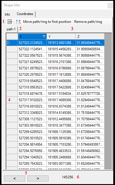
- Remove the selected vertex - Remove the selected vertex(es). The user can select multiple vertexes; the same logic applies to the attribute tables.
- Automatic column width - Adjust the column width to the current view.
- Move path/ring to first Position - Remove Path/Ring - If an SHP contains a multi-polygon, a single record can contain multiple elements; in this case, numerous tabs appear at the top of the coordinates. These functions can help to remove/separate these multi-polygons.
- The coordinates - The user can adjust the coordinates by double-left-clicking on the field and typing in a new value for the selected coordinate.
- Previous - Next item - The user can move between the items inside the SHP file with these arrows.
- Record number/Total record number - The user can see how many records can be found in the active SHP and which one the user inspects. When moving between records with the arrows, the number will be updated.
To close the window/finish the command, press the right-click or the ESC button.
- Create New Point/Polyline/Polygon - Create a new element of the active SHP type. The icon represents the currently active SHP type. After the user starts the command, the mouse cursor will change from mouse pointer to crosshair, and the user can start drawing in 2D or 3D windows. Pay attention to the snap modes when starting the drawing. After the user uses the tool, the software will remember the last used snap mode settings until the restart of the software. If the user draws a polygon, it is not required to click on the start point to close it; the software will automatically connect the start and end points. If a point is placed, it will be placed instantly. If a polyline is extracted until the user does not press enter or double-left click, the line appears red (not accepted), and if the user is satisfied with the result, press enter, and the line takes the SHP layer colour. Suppose the user places a polygon until the user does not press enter or double-left click; the polygon appears as red (not accepted), and it turns into a polygon only and takes the SHP layer colour if enter is pressed or double-left clicked to close the drawing. If the user works on a polyline or polygon but does not accept the lines (they appear red), changing a tool (for example, starting a modify command) will clear the current line. The user won't be able to accept it anymore. Sometimes, a glitch of the line remains in the view until the user starts a new line. When a polyline or polygon is being extracted with this tool, and one or more vertexes are misplaced, the user can press right-click to undo the last vertex. This can be done multiple times until the last vertex (the first of the polyline/polygon) has been removed. If the user removes one or more vertex with a right-click and continues to extract the polyline, the previously removed points will appear as red dots, indicating for the user where the last vertex was. This might seem like a glitch for the inexperienced user, but it's a guide to track where the points were before. If the user starts the tool, but no extraction happens, or the user accepts the last temporary line, the right click will close the command, and the user gets back the mouse cursor. As long as the user does not stop the command, it is possible to continuously extract new elements (the polylines and polygons need to be closed, but the command shall not be started again). If the user presses the ESC key, the command will be stopped instantly, the so-far extracted polyline/polygon parts will be dropped, and a glitch of the temporary line might remain, which will disappear after the user starts a new command. This command uses the currently active template in the attribute table.
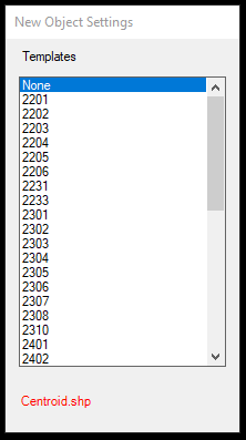
- Create New Point/Polyline/Polygon by template - The same as the Create New Point/Polyline/Polygon command, but it will not use the active template. Instead, it will prompt the template list from the active SHP attribute table so the user can select directly before extracting the element.
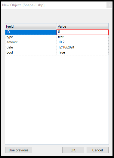
- Create New Point/Polyline/Polygon by Attributes - The same as the Create New Point/Polyline/Polygon command, but it will prompt all available attributes to be filled, according to the attribute types. As PCS supports string, numeric, data and boolean values, all of these types are supported. Set the attributes and press OK to store the values, or use the previous to fill the fields based on the last setting. The function will ignore the current template, it will ask the user for the input anyway. When Cancel is pressed, the user can continue the extraction (for polylines or polygons). Pressing OK will store the geometry as well.
- Move SHP Vertex - The user can move a single vertex using this command. After starting the tool, the snap mode will be locked to vector snap. The tool requires the user to select a vertex. If the vertex is selected, the element that contains the vertex (or, in the case of point SHP, the point itself) becomes selected in the attribute table, and the tool resets all other selections for the active SHP. After the vertex is selected, the snap modes are released, and the user can pick any snap mode and move the vertex to the designated location. If the vertex is moved, the command goes back to "selection mode", so the user can pick a new vertex to be moved, and the snap settings will be remembered. In that way, the user doesn't need to restart the command for each vertex move - it can be started once, then pick-place the points. If a vertex is selected, pressing the right mouse button will "release" the selected vertex, and the user can select a new vertex to be moved. The right mouse click will stop the command if no vertex is selected. The user can also stop the command by pressing ESC. After selecting a vertex, the user can stop the command using the ESC key. In this case, the element remains selected.
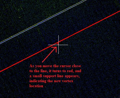
- Insert Shape Vertex - The user can insert additional vertexes into polylines and polygons. It can be used on the active SHP only and not while the active SHP is point type. The tool can also be used in 2D and 3D, but the behaviour is slightly different in the two windows. We recommend that, whenever it's possible, use the 2D view to add a new vertex. In 2D view, the user will see a small support line if the mouse hovers close to a line where the vertex shall be appended; this will help the user indicate where the vertex will be placed, and the affected line turns red.
The vertex elevation will be calculated based on the existing line's location. The tool, by default, starts with free point, point cloud and vector snap modes. We do recommend keeping these on. For a 2D view, it is not as important, but if the user adds a vertex in 3D, the snap setting is essential.
In 3D vertex insertion, there is no support line. Most commonly, there should be a point cloud around the place where the new vertex will be appended. If it's a "free-standing" line segment with no other vertexes or point clouds, the software might be unable to interpolate the proper position. In these cases, we do recommend using the 2D view. If the user turns off some of the snap modes, especially point cloud snap, the tool might be unable to append the vertex. The software remembers the last used snap settings for this tool.
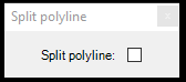
The user can append multiple vertexes after the start of the tool; there is no need to start it again. A Split Polyline window with an unchecked checkbox will appear upon starting the tool. If this option is checked, the new vertex will split the polyline into two parts at the new vertex location, and both polylines will inherit the initial vector's attributes. This cannot be used for points or polygons.
- Clip polygon with polyline - This function allows the user to clip a polygon with a polyline drawn by the user. - Currently unavailable function.
- Clip polygon with 2 vertices - This function allows the user to clip a polygon "with a straight line"; in other words, the user can pick two vertexes, and the polygon will be split into two polygons. The tool locks the snap mode to vector snap. After selecting the first point, the selected polygon becomes selected. After picking the second point, the software will ask the user whether or not the original polygon shall be kept. The split polygons will inherit the original polygon's attributes. The tool will reset the active SHP selection.
- Merge - This tool allows users to merge connected polygons. Not connecting polygons cannot be merged. The tool locks the snap mode to vector snap. The user can select the two polygons, which will be merged, and the common side will be erased. The attributes of the FIRST SELECTED polygon will be kept during the merge. It works only for polygon objects; this tool cannot join polyines. The tool will reset the active SHP selection.
- Remove Shape Vertex - This tool allows users to remove vertexes from polyline or polygon objects. The tool cannot be used on point SHP, polylines cannot have fewer vertexes than two, and polygons cannot have fewer vertexes than three. If the user tries to do so, the software will warn the user it is impossible. The tool locks the snap mode to vector snap. Starting the tool will reset the active SHP selection.
- Join SHP polylines - This function can join polylines and works only for polyline-type SHPs. If a non-polyline SHP is the active SHP, the software will warn the user that the operation cannot be started. The tool locks the snap mode to vector snap. The user shall select two polylines. If the polylines are connected with a common vertex, that location will be the connection point, and the two polylines will be joined. If the two polylines are not connected, the first selected polyline's endpoint will be connected to the second selected polyline's start point. The joined polyline will inherit the FIRST SELECTED polyline's attributes. The tool will reset the active SHP selection.
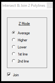
- Intersect + Join SHP polylines - This function allows the user to extend and join two polylines in 3D. It works the same way as Join SHP polylines, but the not joined polylines will be intersected against each other, the polylines will be extended, and the intersection will be placed as a vertex. When the user starts the tool, a window will appear, which allows the user to set the elevation of the intersection, allowing a higher level of control over elevation questions. It is also possible to intersect the two lines but avoid the join by unchecking the join option in the settings window.
- Split SHP Polylines - This function will split a single polyline for two polylines at the selected vertex location. It cannot be used with points or polygons. The function will lock the snap modes to vector snap. The split polylines will inherit the original polyline attributes. The tool will reset the active SHP selection.
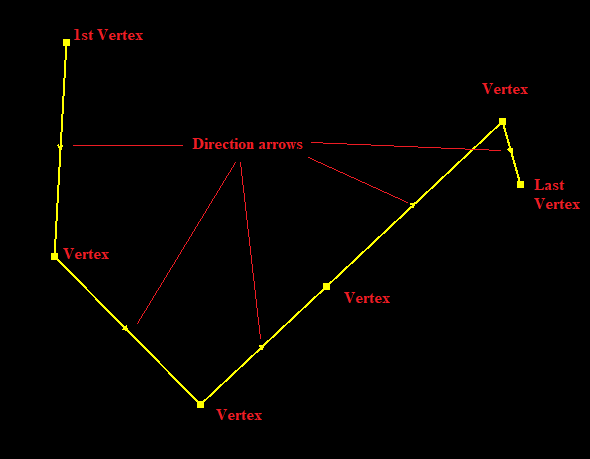
- Reverse Geometry - The polylines have a direction the same as the user draws, so the direction goes from the start point towards the endpoint. Upon selecting a polyline, the middle point between two vertexes shows an arrowhead, which represents the direction of the polyline. In some cases, this direction is essential. With this tool, the user can invert this direction so the start and end points switch places. The function will lock the snap modes to vector snap. The tool will reset the active SHP selection.
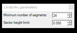
- Circle by 3 Points - Create a circle with three points. The function allows the user to use any snap mode. The function can be used in 2D and 3D views as well. If the user aims for a perfect circle, use the 2D view and adjust the elevation afterwards. If the user uses the 3D view, the circle - despite the best efforts - will never be a "perfect" circle. When the user starts the tool, the configuration window will appear, where the user can set the sector height limit and number of segments. We do recommend using 24 segments for an optimal circle shape. If the circle is extracted in 2D view, a support line will appear in red to show the user what the circle will look like. This feature is not available in 3D view. The function does not reset the active SHP selection.
It is a common goal for the users to have all the vertexes in a single plane. If the circle is placed - as the user uses 3 points, which will define a plane - the points will stay on a single standard position plane. If the user wishes to force all points to a single elevation, we recommend using the Set Z tool if the vertexes are not on the same elevation. See the description below. We would also raise the user's attention to the fact draping might result in a zig-zag line in terms of elevation. The best practice is to place the circle initially in the correct position and adjust all vertex elevations simultaneously, not separately, to avoid elevation issues.
- Arc by 3 points - Create an arc with 3 points. It is the same as a Circle by 3 points, but the user cannot create a complete circle using the tool.
- Circle center + radius - The user can place a circle by selecting the circle's centre point by radius. The user can set the number of segments for the circle. In 2D view the software presents a red support line to help the user place the circle.
- Circle radius + center - The user can place a circle by setting a radius and number of segments in the pop-up panel and place it in 2D or 3D view.
- Ellipse by center and radiuses - The user can place a center point and then pick the a and b sides of the ellipse. In 2D view, the software presents a red support line to help the user place the ellipse.
- Ellipse by 3 points - The user can place an ellipse using 3 points on its perimeter.
- Rectangle by 3 points - Create a rectangle with 3 points. The function allows the user to use any snap mode. The function can be used in 2D and 3D views as well. When starting the function, pick the longer side of the object, then one point at the other side (this other side point is not required to be a corner). If the user aims for a perfectly rectangular shape, use the 2D view and adjust the elevation afterwards. If the user uses the 3D view, the rectangle - despite your best effort - will never result in a perfect 90° rectangular shape element. If the user is extracting the rectangle in 2D view, a support line will appear in red to show the user how the rectangle will look like. This feature is not available in 3D view. The function does not reset the active SHP selection.
- Measure Bounding Rectangle - Create a rectangle with multiple points selected on the outer rectangle of an object. This tool was initially designed for extracting rectangles when the corners are not visible, only a few points on the sides. Use this tool in 2D only. The function allows the user to use any snap mode. The function does not reset the active SHP selection. A support red rectangle will be visible as the user places the points to fine-tune the location.
- Remove Point/Polyline/Polygon item - This function is the standard delete tool. The user can visually select the elements from the active SHP for deletion, both 2D and 3D. The software will not prompt the user for confirmation and deletes the element directly. The function will lock the snap modes to vector snap. Starting the tool will reset the active SHP selection.
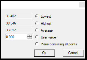
- Set Elevation - With this tool, the user can assign a single elevation value for all vertexes for the selected element. When the user starts the tool, the snap mode will be locked to vector snap. When the user selects an element, the software will inspect all vertex elevations first. Then, a panel will appear where the user can decide which elevation shall be used: the lowest, the highest, or the average (all of these are calculated from the existing vertex's elevation), projected to a plane calculated from all vertices or the user can assign a specific value on demand. Select the respective radio button, and press OK. Then, all vertex will be set to the designated elevation. Starting the tool will reset the active SHP selection.
- Modify Vertex Z - This is one of the most essential tools, along with the drape, to adjust elevation. This tool allows the user to change the elevation of a single vertex with any other elevation that the user can snap to. This allows a swift adjustment of the elevation according to user needs. After starting the tool, the snap mode will be locked to vector snap until the user does not select a vertex. After vertex selection, all snap modes can be used. When the user selects a vertex, the cursor changes and according to the active snap modes, the user can click anywhere in the project, and the elevation will be assigned. The command is continuous, which means that until the user presses right-click, the elevation can be changed unlimited times when the user clicks to a new location. If another vertex needs to be selected, press right-click to release the current vertex and pick a new vertex again. The user can exit the command by pressing right-click (if no vertex is selected), double right-click (if a vertex is selected), or pressing the ESC button. Starting the tool will reset the active SHP selection.
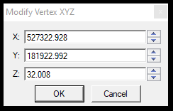
- Modify XYZ - The user can manually modify the selected vertex's XYZ coordinates by typing a new value. When the user starts the tool, the snap mode will be locked to vector snap. Starting the tool will reset the active SHP selection.
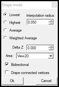
- Drape - Drape is very important for adjusting elevation. The general logic and the developer's recommendations can be read in the draping article. After starting the tool, the settings window will appear, where the user can specify which settings should be used. The drape generally takes one or more vertexes, inspects the vertex's environment and searches for point cloud points within a search radius (an infinite elevation tube). As it finds many point cloud points, it can be set to find the lowest, highest or average from these points, and the tool adjusts the initial vertex's Z value to this found value. The tool will affect all vertexes in the selected element, and - if checked - the connected vertices. After starting the tool, the snap mode will be locked to vector snap. Starting the tool will reset the active SHP selection.
- Drape Vertex - Same as Drape but only affects the selected vertexes and not all vertexes inside the element.
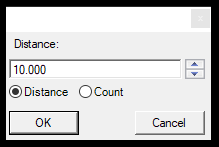
- Divide Section - The divide section tool allows users to add vertexes to polylines or polygons based on distance or by dividing the element for N parts. When the user starts the command, the setting window will appear, where the user can decide if the selected objects will be divided by length or by number of sections. The distance dividing will take the first (and every already existing vertex in the element) and inspect if the distance to the next vertex is bigger than the set value. For example, if the set value is 10 meters, and the distance between the first and second vertex, the software will add a new vertex to 10 meters. As the remaining distance is 2 meters to the second vertex, it will not append a new vertex. If the second vertex is 4 meters away from the third vertex, it will not append the vertex. This iteration will be performed for each existing vertex. If the user selects the count option, the tool will inspect the whole length of the selected element and add vertexes to reach the designated number of segments while ignoring the existing vertexes. The tool cannot split the element; it only appends vertexes. After starting the tool, the snap mode will be locked to vector snap. Starting the tool will reset the active SHP selection.
- Copy Shape - The copy shape tool allows the user to copy the object using the selected vertex. It is the same as "Copy with basepoint" in a CAD environment. After starting the tool, it will prompt the user if the attributes shall be copied as well. The selected element's attributes will be copied to the new object, if yes. If not, the active template will be used. After starting the tool, the snap mode will be locked to vector snap. When the element has been selected, the user can use any snap mode. The tool opens an auxiliary window where the user can check “Copy Multiple Times” option, which allows them to copy the selected element multiple times. If unchecked, after the copy of the element a new element can be selected for copy. The settings window also has an option for Copy Selected. If this option is checked, the selected elements will be copied. Pressing right-click after selecting the element will undo the selection, and a new element can be selected. If there is no element selected, a right-click will stop the tool. Starting the tool will reset the active SHP selection.
- Move Shape - The move shape tool allows the user to move the object using the selected vertex. Same as "Move with basepoint" in a CAD environment. After starting the tool, the snap mode will be locked to vector snap. When the element has been selected, the user can use any snap mode to place the element. Pressing right-click after selecting the element will undo the selection, and a new element can be selected. If there is no element selected, a right-click will stop the tool. Starting the tool will reset the active SHP selection. The tool opens an auxiliary window where the user can check “Move Multiple Times” option, which allows them to move the selected element multiple times. If unchecked, after the move of the element a new element can be selected for move. The settings window also has an option for Move Selected. If this option is checked, the selected elements will be moved.
- Shift by Z - Sort of similar to Modify Vertex Z, but it affects the whole element. After starting the tool, the snap mode will be locked to vector snap. When the element has been selected, the user can use any snap mode. After the user selects the element, all snap modes become available. The user can click anywhere with the respective snap mode. The software will calculate the elevation difference between the selected vertex and the clicked location and prompt a panel where the distance is already set. This set elevation can be modified manually if the calculated elevation does not fit the needs. All vertex will be shifted with the provided elevation. Starting the tool will reset the active SHP selection.
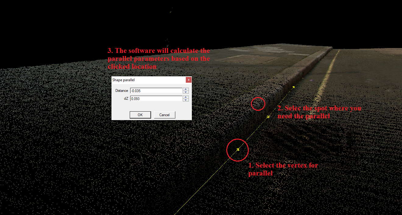
- Parallel - The parallel tool is a 3D tool that allows users to parallel a polyline or polygon visually or based on a parameter. After starting the tool, the snap mode will be locked to vector snap. When the element has been selected, the user can use any snap mode. The user can click anywhere, and the software will calculate the parallel distance and elevation difference based on the clicked location. The parameters can be adjusted manually, and the values can be negative (the right side of the direction of the vector will be positive, the left side will be negative, elevation by meaning). The parallel will be applied for all vertexes. If the parallel is performed in 2D view, a support line will appear, indicating the result parallel line. Please note that the software cannot shorten the number of vertexes if the distance is too low between vertexes as a result of the parallel, and this may result in odd vertex locations in small or dense vertex places. Always crosscheck the parallel lines at corners or dense locations, and remove the unnecessary vertexes if needed. Starting the tool will reset the active SHP selection.
- Insert Midpoint - This function works only with point type SHP/FDB tables. The tool allows the user to use any of the snap modes. The tool will insert the midpoint between 2 selected points. The elevation of the point will be interpolated based on the selected points. The tool will not reset the current selection.
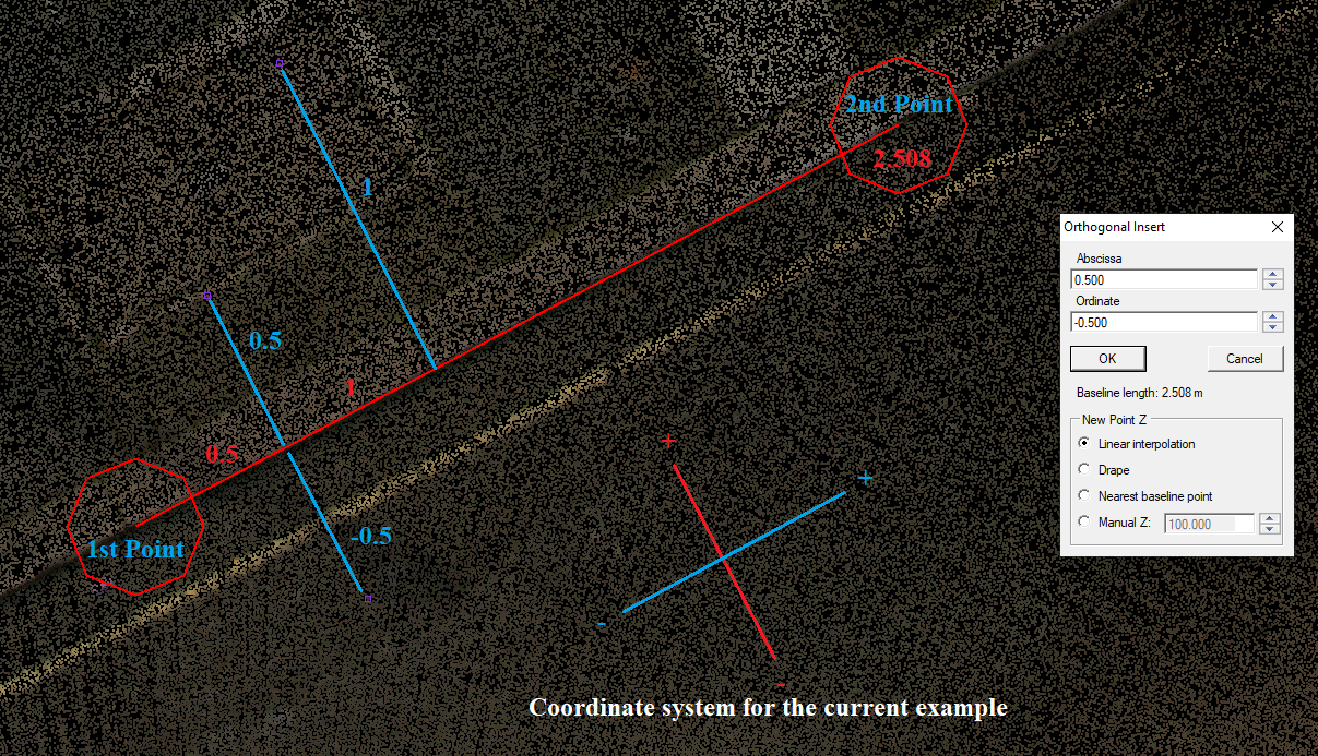
- Orthogonal Insert - This function allows the users to place points numerically using abscissa and ordinate values. The tool can be used only with point SHP/FDB tables. After starting the tool, free point, point cloud and vector snap modes are allowed. The user shall define a baseline, which will be used for the orthogonal inserts. After the baseline is determined, the parameter window will appear. Here, the user can specify two coordinates: the abscissa (the movement along the baseline) and the ordinate (the movement perpendicular to the baseline). In that way, the user can create a perpendicular network of points based on manual values. Both values can be negative; the negative abscissa coordinate will be behind the first selected point. The abscissa can be bigger than the baseline. The ordinate is positive to the left of the baseline and negative to the right. The elevation of the freshly created points can be set in the settings window (interpolated, draped, nearest baseline point or manual Z). Type in the abscissa and ordinate, and press ok, then the point will be created. Pressing OK multiple times will place numerous points. Pressing Cancel will close the settings window, and a new baseline can be created. Starting the tool will reset the active SHP selection.
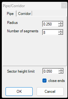
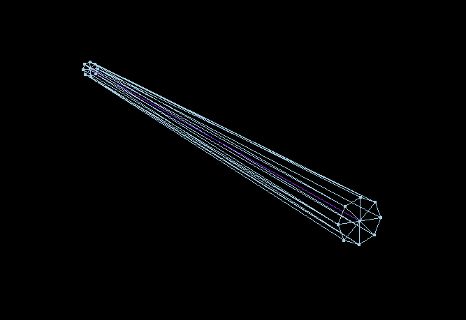
- Pipe/Corridor - This function will generate “pipes” from polylines by taking the active SHP lines as axis for a pipe and generate a 3D polygon display with the given parameters. The generated polygon SHP will has no attributes except the ID field. The generated polygons can be used with the Main Classification Toolbar - Corridor function, where the cloud can be re-classified using these pipes.
In the pipe settings the user can adjust the radius and number of segments. The corridors setting allows the user to insert coordinates where the corridors shall be placed.
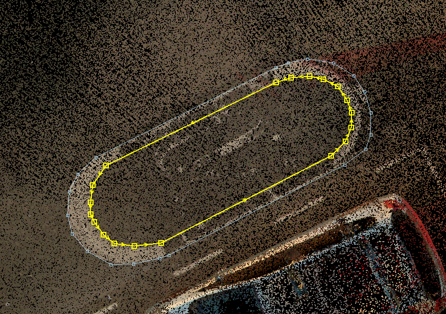
- TSG - Transfer Sub-geometry - This tool can move multiple geometries into a single record or, in other words, create a multi-polyline, multi-polygon or a doughnut polygon. After starting the tool, the snap mode will be locked to vector snap. Select the designated elements, which will merge into a single record. The attributes from the first selected element will be picked. Starting the tool will reset the active SHP selection.
Before TSG:
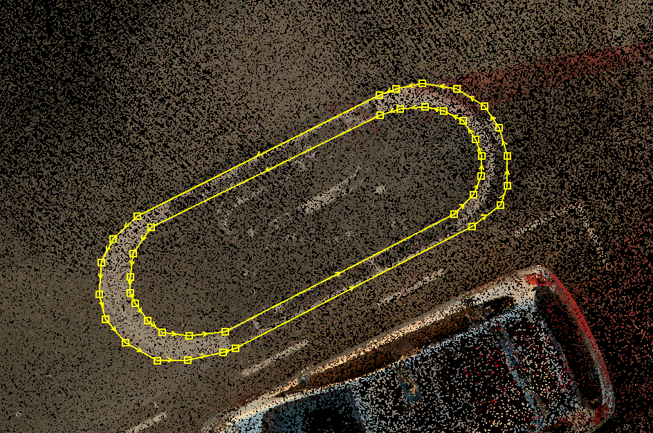
After TSG:
- CG - Copy Geometry - This tool allows the user to move a record between the same type of SHP/FDB tables. For example, if a line is created in A SHP, but the user needs a copy inside B SHP, the user can also use this tool to copy the element to this SHP. The tool can be started only if it's possible to run, so there is a minimum of one more SHP from the same type as the active SHP inside the project. The tool will lock the snap mode to vector snap. After starting the tool, the settings window will appear, where the user can select from the dropdown list which will be the target SHP and if the attributes need to be copied. If the Copy Attributes option is not checked, the target SHP's active template will be applied to the copied elements. If the right-click is not pressed, the user can continuously select elements copied to the target SHP. Starting the tool will reset the active SHP selection.
- MG - Move Geometry - This tool works the same way as Copy Geometry, but instead of leaving a copy at the source layer, it will move the element from the current layer to the target layer.
- SSG - Subtract Sub-Geomtry - The opposite of TSG - if a record contains multiple geometries, the user can subtract parts of it to separate records. The separated records will keep the exact attributes. After starting the tool, select the object with multiple geometries and select the geometry which shall be subtracted from the multi-geometry. After the subtraction, the user can choose a new multi-geometry to subtract again.
- Undo - Undo the last non-classification action in PCS. This applies to attribute value changes as well. The tool is greyed out if there is nothing to be undone.
- Redo - Redo the last non-classification action in PCS. This applies to attribute value changes as well. The tool is greyed out if there is nothing to be redone.
- Undo list - A dropdown list which contains the last commands to be undone with a counter. If the user does undo an action from the middle of the list, all actions between the selected and the last action will be undone. Once the user opens the undo list, the dropdown can be closed only by pressing the ESC button. The tool is greyed out if there is nothing to be undone.
- Redo list - Same as Undo list but with Redo function if the Undo has been used multiple times. The tool is greyed out if there is nothing to be redone.
- Clear Undo Operations - This function lets users clear the undo/redo list. Once used, the user cannot undo or redo the so-far performed actions. The tool is greyed out if nothing is to be cleared from the list.
- TEST - This button serves testing purposes and might not appear depending on your license. Please do not use it without specific instructions from developers. Most commonly, the tool is blind, and when it is pressed, nothing will happen.