¶ Clip Frame Toolbar
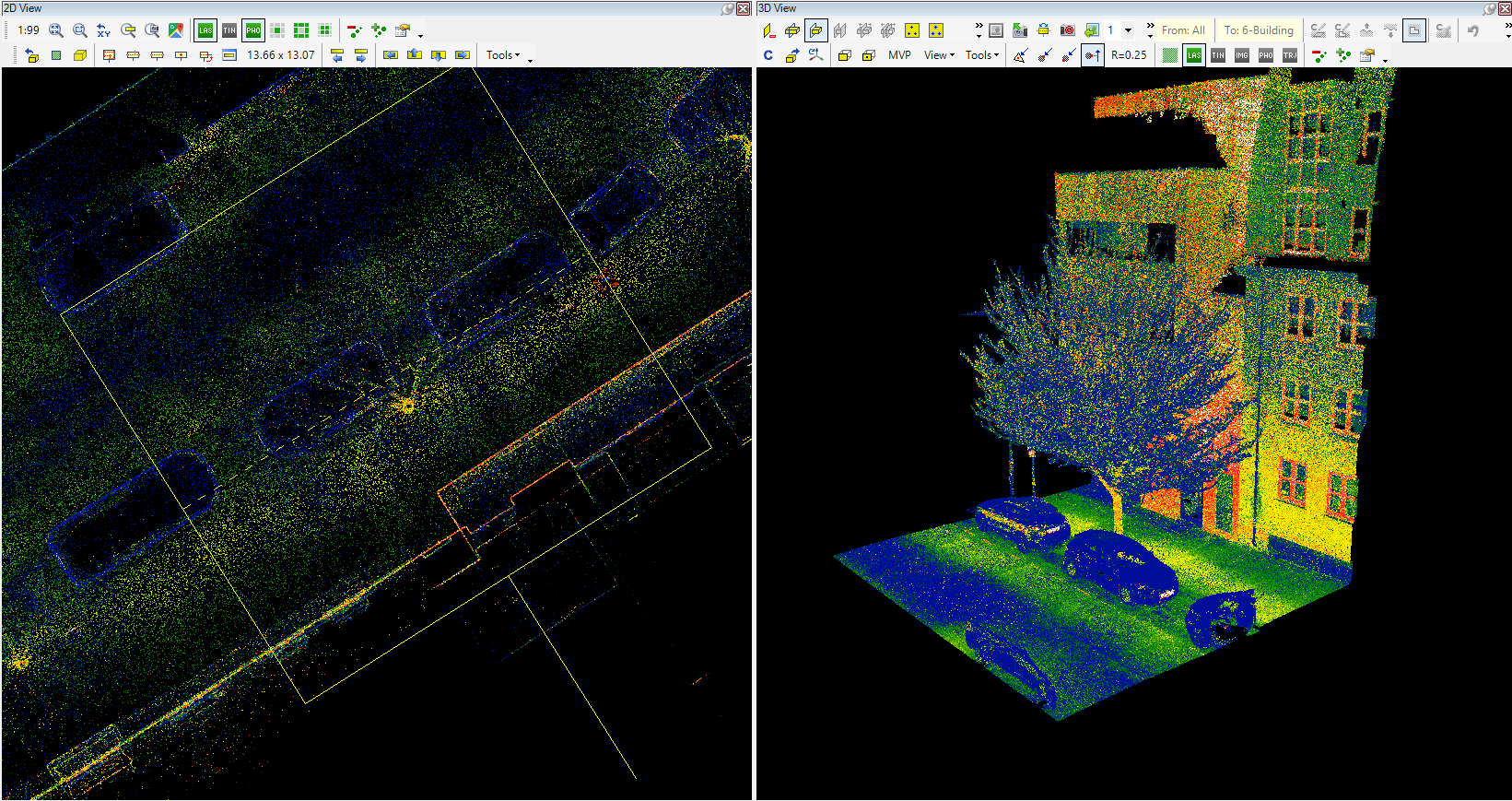
The clip frame is an essential object in PCS: it controls which part of the point cloud will be loaded into the 3D view from all loaded point clouds. Generally, the clip frame is represented by a yellow rectangle with a "handle" on one longer side. The clip frame is always in the 2D view, even if it's not in the current viewport. The clip frame always has to be somewhere. The rectangle can be placed using the toolbar, or if it's already placed somewhere, the user can move, rotate or resize the clip frame as presented below. The "handle" side is the front side; the default display will always show the cloud from this side. The clip frame placement is snap sensitive, so we recommend using free point snap for place the clip frame.

The area the user selects with the clip frame can be seen in 3D view after pressing the reload button on the clip frame toolbar. The user can load as many point clouds to the project as available, as the 2D view is distance-sensitive, which means that when the viewpoint is further from the point cloud, fewer points will be loaded. The 3D view will load all points inside the clip frame, and this function has a limit of 256 million points. If the user tries to load more points into the 3D view using the clip frame than 256 million points, the software will cut the points (the user might experience this as tiles are missing from the 3D view) above 256 million points. Loading a maximum of 100-150 million points to 3D view is also recommended to ensure fluent usage. Standard workstations shall be able to handle 256 million points fluently, but if 256 million points are loaded, the users might not recognise some points were cut during the load. The related logic is described below in the respective tool description.
If the user loads something to the 3D view, but the clip frame is moved, and the cloud is not reloaded after the start of any vector operation, it will refresh the 3D view's vectors to the actual clip frame, but the cloud will remain as it was. In that way, the user might see different vector parts than cloud parts if the view has not been reloaded. For all vectors with a minimum of one point inside or near the clip frame within a few meters, the vectors will also be loaded into 3D view. The same applies to geophoto locations. Rasters will not be visualised in 3D view.
The clip frame toolbar is located in the 2D view. Please note that some icons might be hidden by default.

The description of the tools are the following:
- Reload 3D view - Reload the current extent of the clip frame to the 3D view
Sometimes, the point cloud is not visible after loading into 3D. This issue arises commonly because inexperienced users might be unaware of some of the settings they have made. Please refer to The point cloud is not visible debug guide. After reloading the 3D window, the camera will focus on the middle of the loaded point cloud's extent.
- 3D view source - This switch controls the reload of the complete 2D view with a lower point density. If turned on, the 2D area can be reloaded to a 3D view with a low point density (a few million points total). Please note that this is a toggle function; if it is turned on, it is impossible to get the total point density. The function will load all point clouds to 3D view with the lower density ignoring the clip frame area for point clouds, however, only those vectors will be loaded to 3D view, which are covered with clip frame. If this function is used, the whole area can be covered with the clip frame - even if it's enormous - so the user can inspect the entire cloud with the vector - if the lower density is enough. Keep in mind that if the function is turned off, the software will reload the 3D view based on the clip frame, and if the whole area is covered with the clip frame, the software will try to load the entire area to 3D, which will undoubtedly too big for the software. In this case, the best practice is to let the software load, which will cut the cloud at 256 million points, resize the clip frame, and reload a smaller area again. If the user clicks inside any PCS window while it tries to load the complete cloud to 3D, it might crash the software.
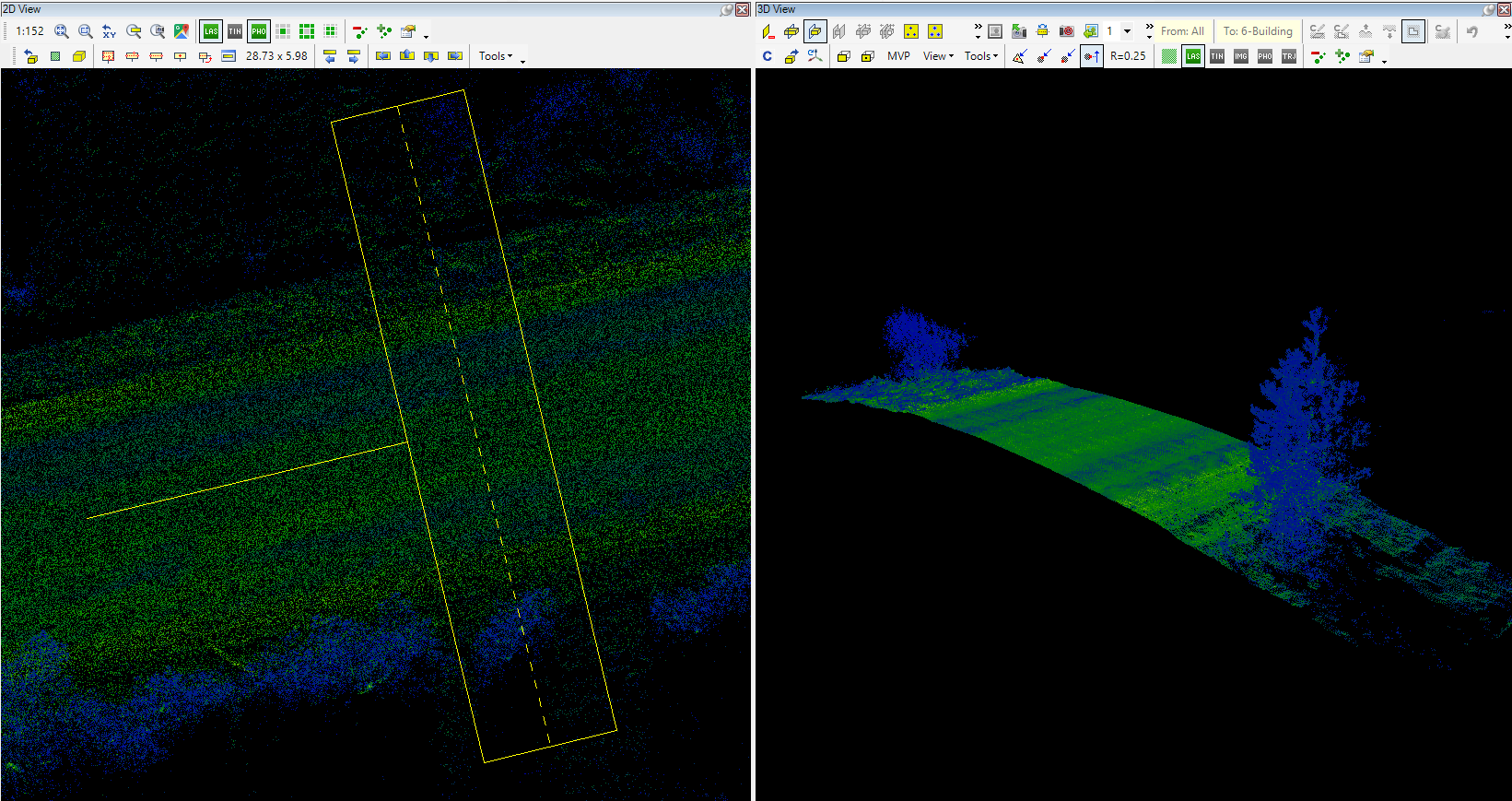
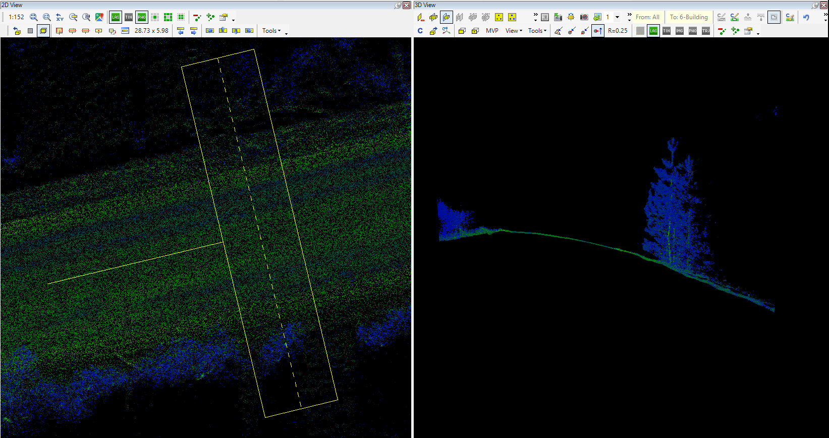
- Profile Mode - This switch controls the profile mode, forcing all point clouds inside the clip frame area to be moved to a single plane, the axis plane of the clip frame. This tool is handy for extracting sections or facades from the point cloud, as it forces the point cloud to a single plane. The clip frame axis snap mode becomes available when this function is activated. The direction - from which you will inspect the cloud in 3D after reload - is the same as the clip frame's front side (where the small "handle" can be seen). The 3D window classification toolbar becomes only active when the profile mode is used, and all point cloud points are loaded into the memory (see LAS optimization article for more info about part/all points in memory).
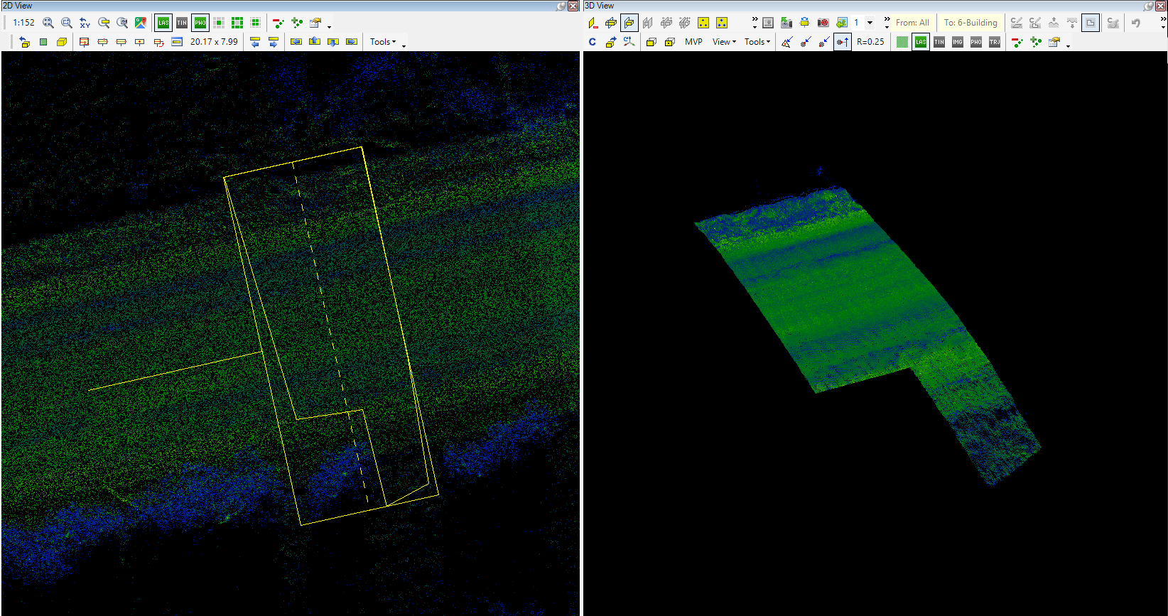
- Place clip-frame (polygon) - The user can draw a polygon in the 2D view, and the polygon area will be loaded to the 3D window. If this method is used, an additional line - the polyline that the user draws - will appear inside the clip frame rectangle; this represents the area to be loaded into 3D. The Clip frame rectangle remains and will occupy the largest part of the selected location. In some cases, if the polygons are concave, the clip frame rectangle might appear not to cover the polygon wholly. In these cases rotate the clip frame rectangle to cover the whole polygon, otherwise the intersection of the polygon area and the clip frame rectangle will be loaded to 3D window only. The last placed vertex can be undone by right-clicking, just like in vector extraction. To instantly cancel the operation, press ESC.
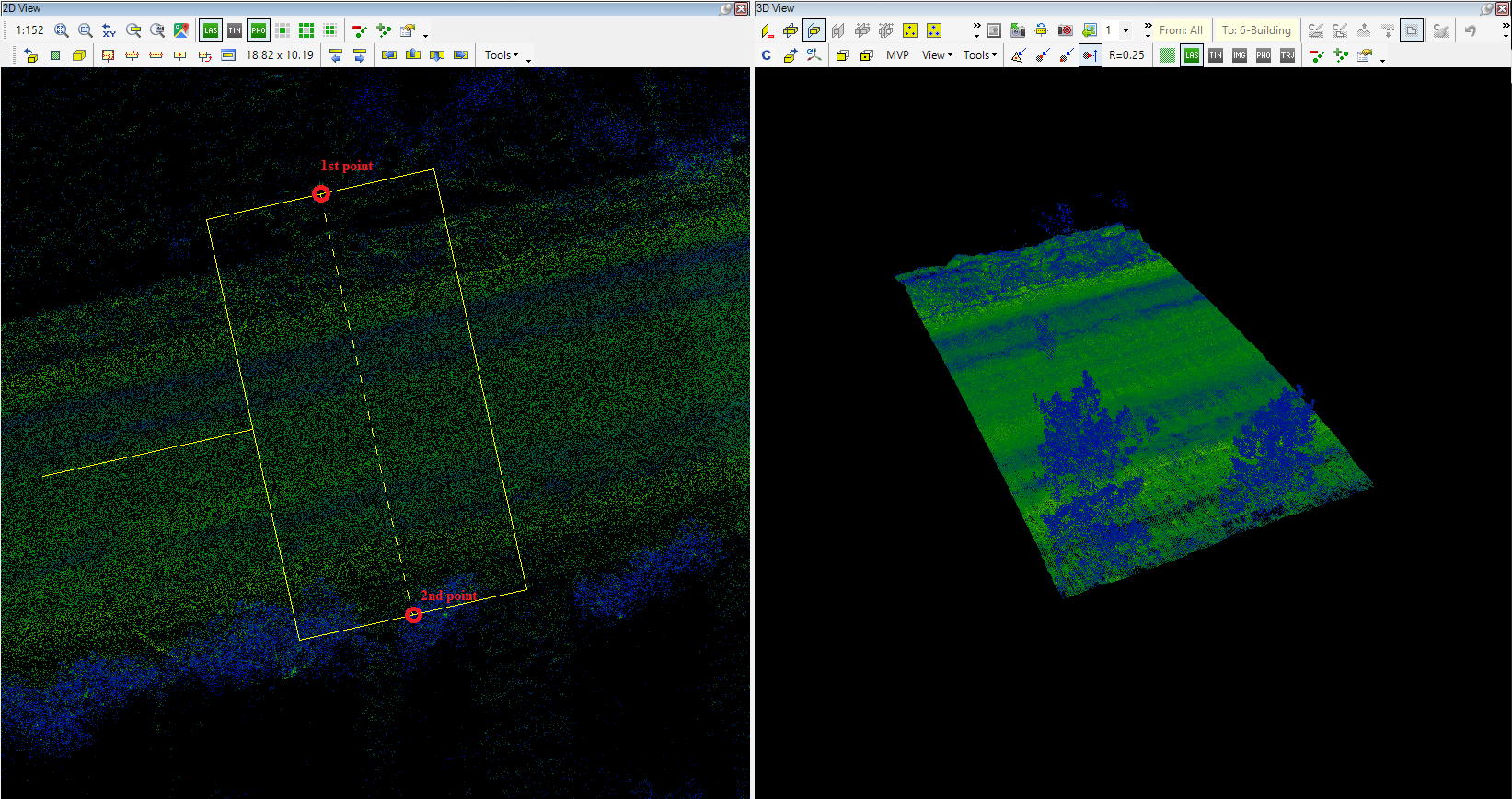
- Place clip-frame (3pt) - Place a clip frame using 3 points (2 axes and one width). When the function is started, the user can place a rectangle with 3 points: first, select the first point of the axis, then select the second (the distance between the 2 points will be the length of the clip frame), then the width of the rectangle can be adjusted with the 3rd click. This is the most commonly used clip frame placement method.

Place clip-frame (2pt) - Place a clip frame using 2 points (2 axis points, width used from the previous clip frame). When the function is started, the user can place a rectangle with 2 points: first, select the first point of the axis, then select the second (the distance between the 2 points will be the length of the clip frame), and the software will take the width from the previously used clip frame. As the clip frame placement is snap-sensitive, if vector snap is used, The clip frame can also be aligned with section axes.
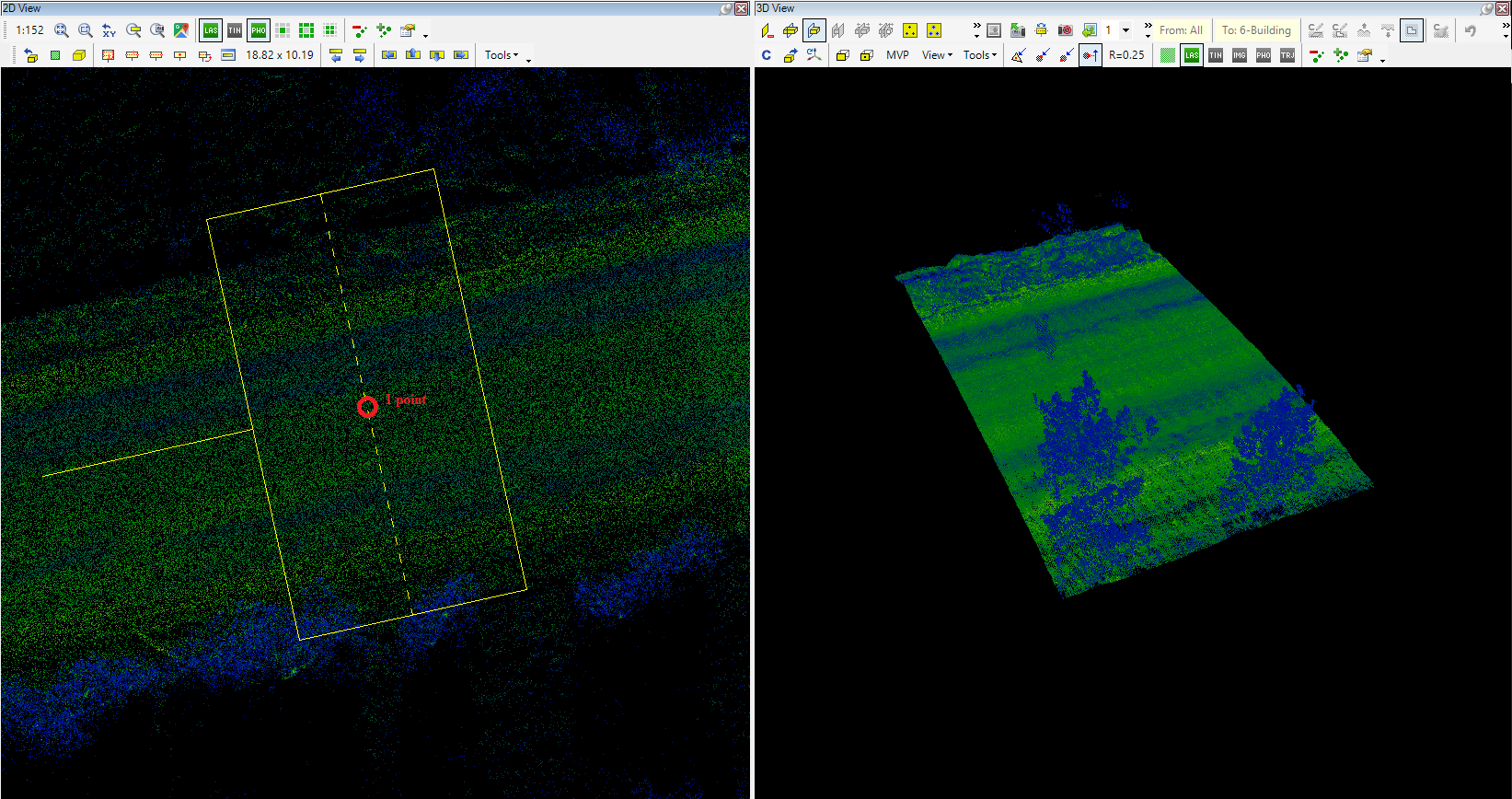
- Place clip-frame (1pt) - Place a clip frame using a single point (specify the centre point of the clip frame; the dimensions will be used from the previous clip frame). When the function is started, click where the clip frame's centre point is needed, and the clip frame will be moved to this location with the previously used dimensions. As the clip frame placement is snap-sensitive, the user can place the clip frame precisely to a point if vector snap is being used.
- Swap sides of clip-frame - With this function, the user can "rotate the handle" around the clip frame, changing the front side of the clip frame. Pressing it once will rotate the clip frame front 90 degrees counter-clockwise. This can be useful if the profile mode is used, but the user needs to inspect the plane from a different perpendicular angle.
- Move Clip-frame to Center - This function will instantly move the clip frame's centre point to the centre point of the current 2D view. This is a "call" button; the user can bring the clip frame to the current location in 2D.
- Clip-frame Settings - This panel controls the clip frame's size and dimensions.
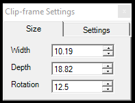
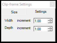
The user can control the clip frame size in meter dimensions in the size tab. Rotation is understood for the front side counting counter-clockwise from the +X axis. The clip frame width and depth increment can be set for the increase-decrease width-depth tools.
- Previous/Next Clip Frame - These buttons can move between previously LOADED clip frames. For example, if the user moves the clip frame but realizes something has been forgotten in the previous one, press the previous clip frame button, and the software will load back the previous state. This function does not work with polygon clip frames. If the previous clip frame was a polygon, only the extent rectangle can be loaded. If a clip frame is placed but has been moved without loading the content to 3D, it is impossible to return to this state; previous and next clip frame functions only allow moving between loaded clip frames. By default, these buttons are not visible on the toolbar. Use the small black triangle at the end of the toolbar to allow these buttons in the toolbar.
- Increase/Decrease Width/Depth - These four buttons can increase and decrease the width and depth for the clip frame with a fixed value set in the Clip-frame Settings. By default, these buttons are not visible on the toolbar. Use the small black triangle at the end of the toolbar to allow these buttons in the toolbar.
- Move clip frame Left/Upward/Downward/Right - These four buttons can move the clip frame in 4 directions. The movement will shift - by default if displacement is 100%, description below - the clip frame to the left with the width of the clip frame, where the left edge of the original location becomes the right edge. In that way, the user can move along the point cloud to cover the whole area with the clip frame. By default, these buttons are not visible on the toolbar. Use the small black triangle at the end of the toolbar to allow these buttons in the toolbar.
- Displacement % - Set the displacement of the clip frame. The default value is 100%, which means that if the clip frame is moved to any direction with the Move clip frame Left/Upward/Downward/Right function, there will be no overlap between the clip frames; they will "join” by the edge. If the displacement is modified, for example, 50%, the movement will leave a 50% overlap between the old and new positions. If the user moves along the point cloud with these move functions and a little overlap is needed, decrease the displacement %. It can be helpful for classification tasks. By default, this button is not visible on the toolbar. Use the small black triangle at the end of the toolbar to allow these buttons in the toolbar. After adjustment of the displacement value, use the ESC key to leave the setting box.
- Tools dropdown - This menu contains additional tools for the clip-frame-related functions.
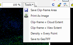
The description of the tools are the following:
- Save clip-frame Area - The software will clip the point cloud to a separate LAS file for the clip frame area (polygon clip frame can be used here). The export will consider the 2D window's" active classification filter settings. This tool is perfect if the user needs a subset of the cloud or you need to pick a detail. Profile mode will be ignored if it's turned on.
- Print As Image - Print the 2D view to a tiff image. - Currently unavailable function.
- Clip-frame = Cloud Extent - This function places the clip frame to the cloud extent. The user can select the active, visible, and all clouds.
- Clip-frame = View Extent - This function will place the clip frame to the current extent of the 2D window.
- Density = Every Point - Currently unavailable function.unavailable
- Save to GeoTIFF - Save the current 2D view as GeoTiff as is. The GeoTIFF will be georeferenced and can be loaded to PCS.