¶ Surface-Cloud difference
The surface-cloud difference toolkit was implemented in Q3-Q4 of 2024, and it can be very helpful in checking vector drawing quality against a point cloud, highlighting the issued locations. The tool does not require the user to be familiar with the Basic or Advanced extraction guides in terms of running the tool, but to correct the errors, it does.
The tool shall have access to point clouds and a surface for the respective area where the function can be used. The surface shall be a TRI file in PCS, which can be imported from DXF/DWG files or generated within PCS. See the respective articles for more info. The surface generation is not discussed in this article. The initial state for our example is that we have a cloud and TRI surface generated purely from vectors using the Triangulator. Before using the Triangulator, make sure that the topology in the linework is perfect in 3D, as the triangulator might be unable to solve topological errors and crash or fall into an infinite cycle. Use the Topology toolbar to eliminate these errors, and read the surface generation manual for further info.


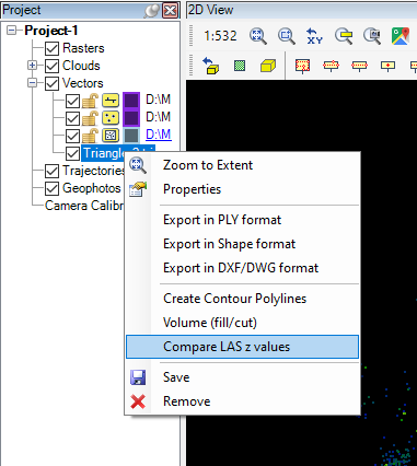
The tool that shall be used is the Compare LAS Z values, which can accessed by right-clicking on a TRI file.
After the tool is started, the settings panel will appear:

The user can set the settings in this panel. The Compare LAS Z article specifies all settings, in this guide we focus more on usability.
The user shall consider the purpose of the vector extraction, the designed accuracy and the source data type. The above-seen settings are suitable for high-accuracy surveys - where the surface should match the cloud close. If the area is more like dirt roads and vegetation, the settings can be lifted with a few cm. If the source data is not from a TLS or MLS sensor (or a lower-grade TLS or MLS sensor), the expected result might be noisier. In the case of ULS or ALS scans, higher intervals shall sometimes be set for tens of centimetres or even meters. Make sure you are using the correct settings.
The tool will generate rasters, which will be tiled, as a geotiff has a limited size. The generation progress can be tracked in the progress bar; the generated rasters will be automatically added to the project.

Pay attention to the result, as the issued areas are between vertexes. The vertexes (the triangle intersections) are usually in the right spot, but if the number of vertices is insufficient, the middle part of the triangle might float from the cloud. This can be normal - in our case, it is visible at the flower patches in the middle island, so it is expected to have more significant red spots there - or can highlight an error. If the vertex area is issued, that vertex is too low or too high. If the error happens on a flat surface or the distance between the surface and the cloud is not allowed, the user shall fix the original linework using tools from the Shape Toolbar or Shape Toolbar 2. After the vectors are fixed, the surface shall be rebuilt, and the compare process shall be re-run. This can be iterated as often as the user needs to achieve the designed quality vectors.
The generated rasters can be used for internal control or provided to the clients to prove the accuracy.