¶ Main 3D Toolbar
The main toolbar is one of the biggest among the 3D view toolbars and contains multiple tools which can adjust the display of the 3D view.

The description of the tools is the following:
- Filter by Classification - This tool will open the Class Filter Window to control the displayed classes in 2D and 3D views.
- Reload - Reload the 3D view based on the current location and size of the clip frame.
- Toggle Pin Mode - Currently unavailable function.
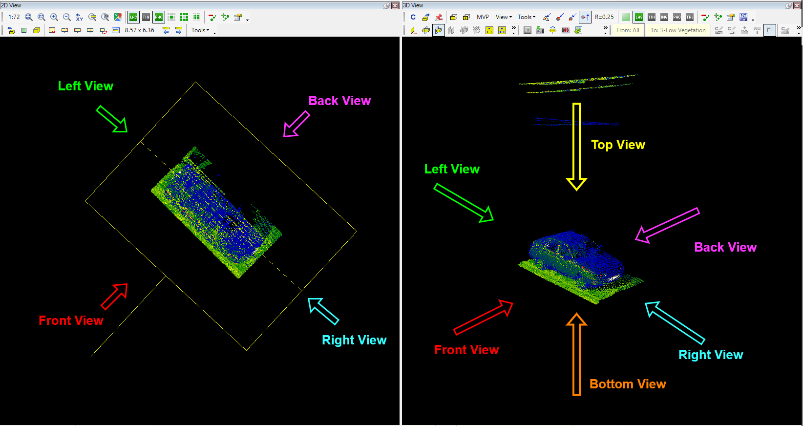
- Front View - Set the camera to the front view position, adjusting the rotation centre to the centre of the point cloud mass loaded into a 3D view. The "front, left, right and back" description can be read below.
- Front View (keep target point) - Set the camera to the front view position, keeping the current rotation centre. The "front, left, right and back" description can be read below.
- MVP - Mirror View Point - The camera direction will be swapped with 180 degrees.
- View dropdown - This dropdown contains all pre-defined views from all sides. The understanding of the view sides (universal everywhere in the software) is the following:
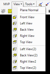
The view dropdown offers the following pre-sets:
Plane normal - The auxiliary plane's normal direction.
Front/Left/Back/Right/Top View - Set the camera position to the selected view position, adjusting the rotation centre to the centre of the point cloud mass loaded into 3D view.
Left/Bottom/Right/Top View (2) - Set the camera position to the front view position, keeping the current rotation centre.
- Tools Dropdown - A few additional tools are available under this dropdown.
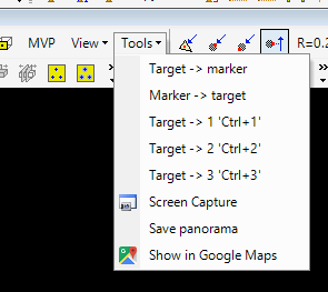
The description of the tools is the following:
Target - Marker - Set the target point to the marker location. See the Target and Marker point article.
Marker - Target - Set the marker point to the target location. See the Target and Marker point article.
Target - 1 'Ctrl+1' / Target ? - 'Ctrl+2' / Target ? - 'Ctrl+3' - Set the target point to one of the auxiliary plane definition points.
Screen Capture - Capture the 3D view as a .BMP file. The capture will contain all vectors, temporary linework and the position of the marker point and the target marker (if turned on).
Save panorama - The software will generate a PanoCube panorama from the viewpoint of the target point. The generated files will be saved to C:\Users\<own user>\Documents\PointCloudScene\PanoCubes. There will be seven images - 1 merged and one front, left, right, up, down, back. The panoramas will include all vector linework.
Show in Google Maps - This tool opens the Google Maps Window based on the centre of the clip frame. This function works properly only if the projection has been set inside the Project Explorer.
- Ridge detection - Find Nearest - Find Farthest - Find Ortho - These settings allow the user to adjust the 3D click while using the point cloud snap. The default selected snap is Find Ortho, which is recommended to be kept as a default. Only experienced users shall adjust this setting. The find nearest and farthest will select the nearest or farthest point cloud point within the specified search radius. The find ortho will always pick the point that the user wants. The nearest and farthest might mislead in dense or noisy clouds. The ridge detection snap mode will allow the user to snap to the ridge of planes. After selecting the ridge detection, the control panel will appear, and the cursor will switch to ridge detection mode. The cursor displays the planes according to the settings in the settings panel.
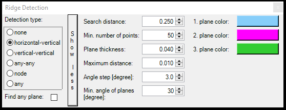
The settings are the following:
- Detection type - The type of planes the user wants to find. The horizontal and vertical are understood in the global coordinate system.
- None - No planes will be found
- Horizontal - Vertical - The tool will search for a vertical and a horizontal plane's intersection point at the cursor location. Useful for ground-wall intersections.
- Vertical - Vertical - The tool will search for a vertical and another vertical plan's intersection. Useful for wall-wall intersections.
- Any-any - The tool will search two standard planes independently from horizontal and vertical dimensions. It will search for the intersection between planes defined by the points at any position.
- Node - Intersection of 3 planes of any position
- Any - Find a single plane in any position
Search distance - The distance in which the software will interpolate the planes.
Min. number of points - The minimum number of points the point cloud shall have to identify a plane.
Plane thickness - The maximum thickness of the point cloud. Within the set thickness, the tool can identify the plane.
Maximum distance - The maximum distance between the discrete points defining the plane.
Angle step - The angle step defines the search radius in terms of angles when standard planes are searched.
Min. angle of planes - The minimum angle at which the software will search the standard planes.
The ridge detection snap will be used if the user uses the new element or other creation tools. It does not overwrite the snap modes, but it will fine-tune the placement of the vertex. It can be used only with point cloud snap.
- Search radius - The search radius for the nearest and farthest snap modes. The default value is 0.25, and only experienced users are recommended to adjust this setting.
- Show fewer points toggle - This toggle allows the users to reduce the number of visualised points in 3D view. This reduction is the same as the default reduction when the user rotates the point cloud in 3D view. Please remember that this is a toggle function; the reduced density will remain if turned on. The toggle does not affect the number of loaded points; even if turned on, all points from the clip frame area will be loaded into 3D view, but the display is reduced.
- Show Clouds - Turn on and off the point cloud display. This toggle turns the point cloud display on and off only for 3D viewing. This setting is remembered after the restart of the software, so make sure it is turned on if the cloud is not visible. If it's turned on but the cloud is still not visible, check the point cloud is not visible article.
- Show TIN - Turn on and off the on-the-fly TIN display for the 3D view. The visualised TIN is not generated physically; it only has a display purpose. The triangle colours are adjusted to the current display, so it is possible to utilize this function for all colouring options. Please note that the 3D view TIN has limitations and can effectively use up to a few million points. A standard TLS or MLS cloud will overload the graphical display and crash the software. It is strongly recommended that the user not use this option above 2 million points without prior testing of your hardware. This tool can be effectively used with ULS or ALS datasets. Using the function will increase the 3D view's reaction time.
- Show ESRI Grid Files - The function is currently under review.
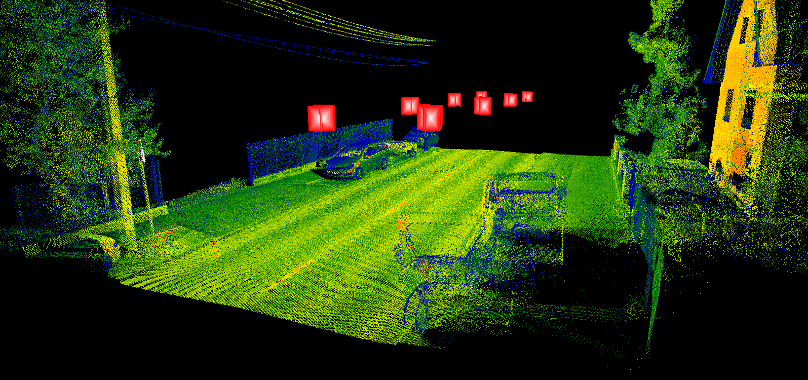
- Show Geophotos - Turn on and off the visualisation of the geophoto locations and directions. The geophotos are displayed as a red pyramid, where the top is the focus point, and the pyramid's base is the image plane. One marker will be presented for each camera device. If the camera devices are located next to each other (exact case), they might appear close to each other (for example, Ladybug Camera).
- Show Trajectory - Turn on or off the trajectory display.
- Toggle 3D Marker - Turn on/off the 3D marker point. The button is displayed with a red highlight if turned on.
- Decrease/Increase point size - Decrease or increase the point size in the 3D view display.
- PLY export - The software can save the clip frame area in a .PLY format. This result PLY will be the same as the user would use the TIN display tool. In that way, every point will be triangulated against each other.
- 3D view settings - The user can adjust the 3D view settings in this panel. See the descriptions below.
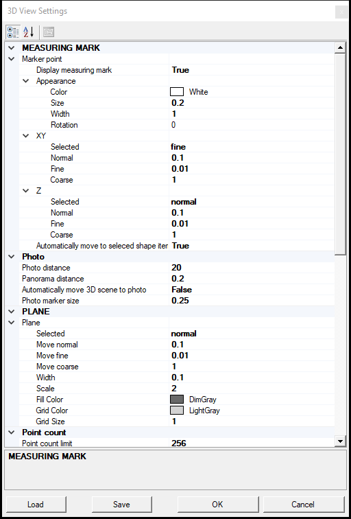
MEASURING MARK - Marker Point - Display measuring mark - This setting can turn the marker point's display on and off.
MEASURING MARK - Marker Point - Appearance - These settings allow the user to adjust the marker point's size, colour and rotation.
MEASURING MARK - Marker Point - XY and Z - These settings are disconnected.
Photo - Photo distance - The distance within which the point cloud will be displayed if the geophotos are active.
Photo - Panorama distance - When the user selects a geophoto, the software will inspect the environment within this distance, and if multiple images can be found within the software will generate a panorama from the photos.
Photo - Automatically move 3D scene to photo - If the setting is set to True, upon moving between the geophotos, the clip frame will be moved to the geophoto location, and the point cloud will be automatically reloaded.
Photo - Photo marker size - The size of the geophoto marker in 3D view.
PLANE - Plane - The user can adjust the palen movement type, plane movement values, plane size and scale dimensions, and the plane's colour and the grid under these settings.
Maximum number of points - This setting controls the maximum number of points which can be loaded into 3D view. The default setting is 256 million points, but the actual number depends on the hardware configuration.
Point Size - In this setting group, the user can adjust the Render Point size - which can be adjusted with Increase/Decrease point size for the 3D view - or enable the distance-dependant render size based on a set of distances.
Quick rendering - Quick rendering - If the value is set to True, as the user rotates the 3D view, the point density will be reduced to fewer points to enhance the rotation performance. All points will be visible during the rotation if set to False.
Quick rendering - The degree of limitation - This setting adjusts the fewer points; if set to a higher value, the fewer points will be visible.
Snapping - Search distance - Same as the search radius described above next to the 3D snap modes.
Snapping - SearchRadiusStep - The step count for search radius adjustment.
STEREO - The functionality has been removed.
Using prev.content - Currently disconnected function.
ZOOM - Allows to modify the 3 zoom mode settings - If the user uses the scroll to zoom in and out, the zoom will be performed with the normal zoom distance, but if the user holds the SHIFT button during zooming, the fine value will be used for zoom, and if the ALT button is held while zooming, the coarse value will be used. In that way, the user can fine-tune the zoom experience using hotkeys.