¶ Plane toolbar
The plane toolbar can control the auxiliary plane operations inside PCS for the 3D view. Currently, the auxiliary plane can be represented with a grey plane or a grid. The plane toolbar is looking forward to a general refurbishment in 2024 Q2-Q3.

The description of the tools is the following:
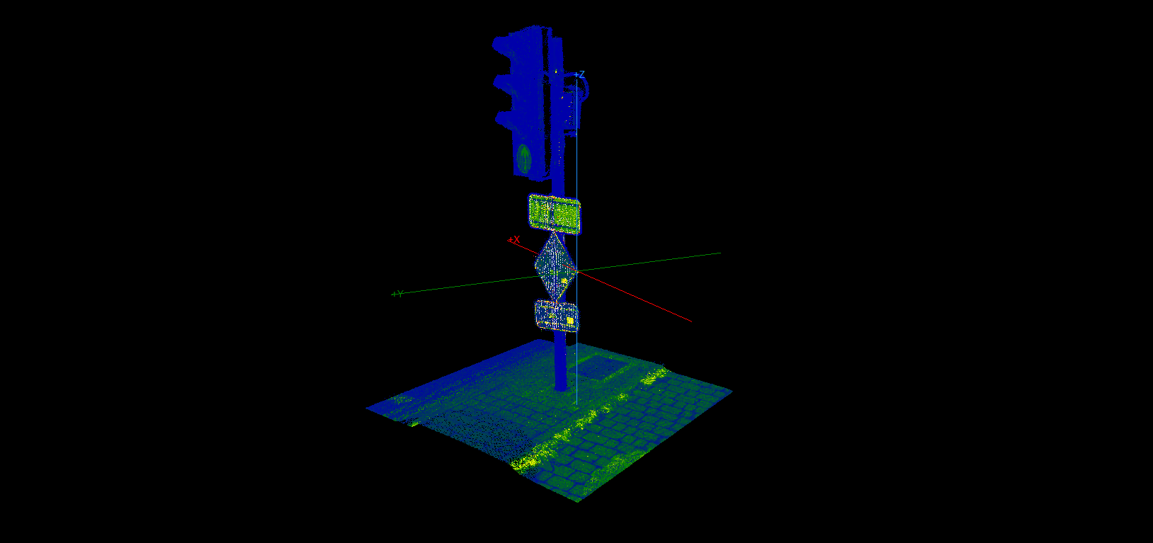
- Toggle Axis - This tool can turn on and off target point visualisation in 3D view. The tool, by default, is not visible in the toolbar.
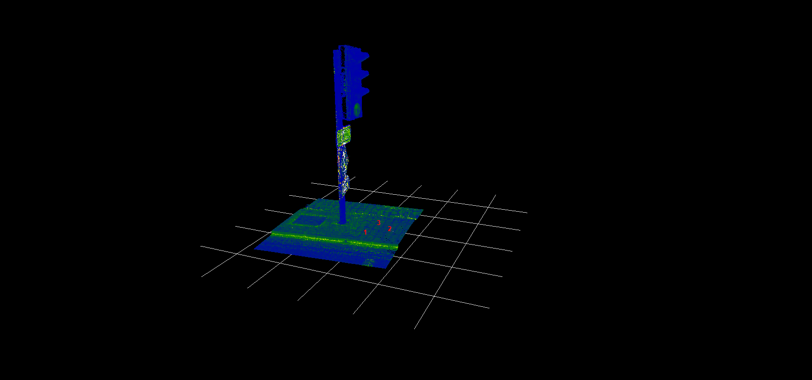
- Toggle Grid - Turn the auxiliary plane visualisation on and off with the grid. The auxiliary plane by default is not in view, the plane shall be moved to see the grid or the plane. See the description below. The grid is infinite, but the visualisation is limited to the clip frame area.
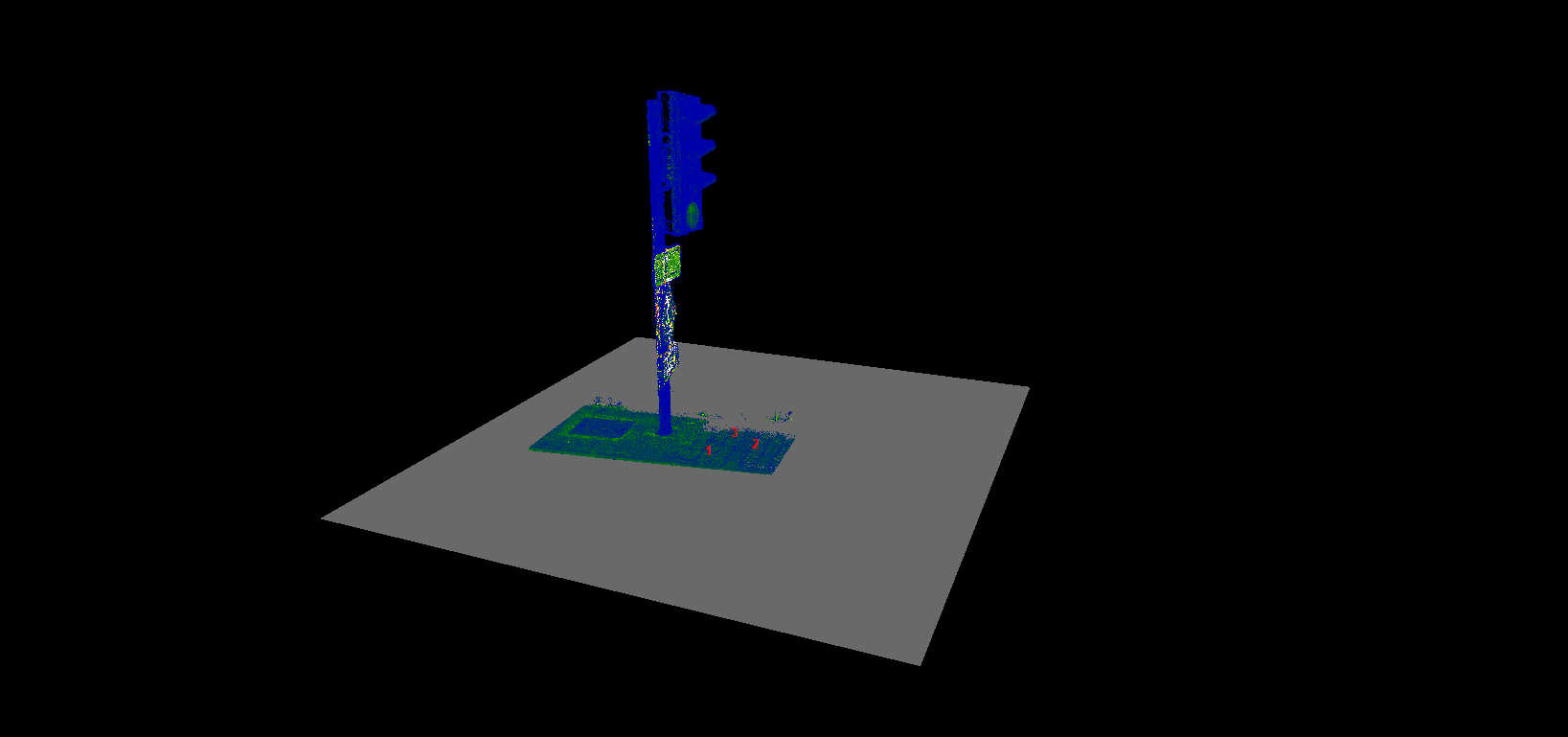
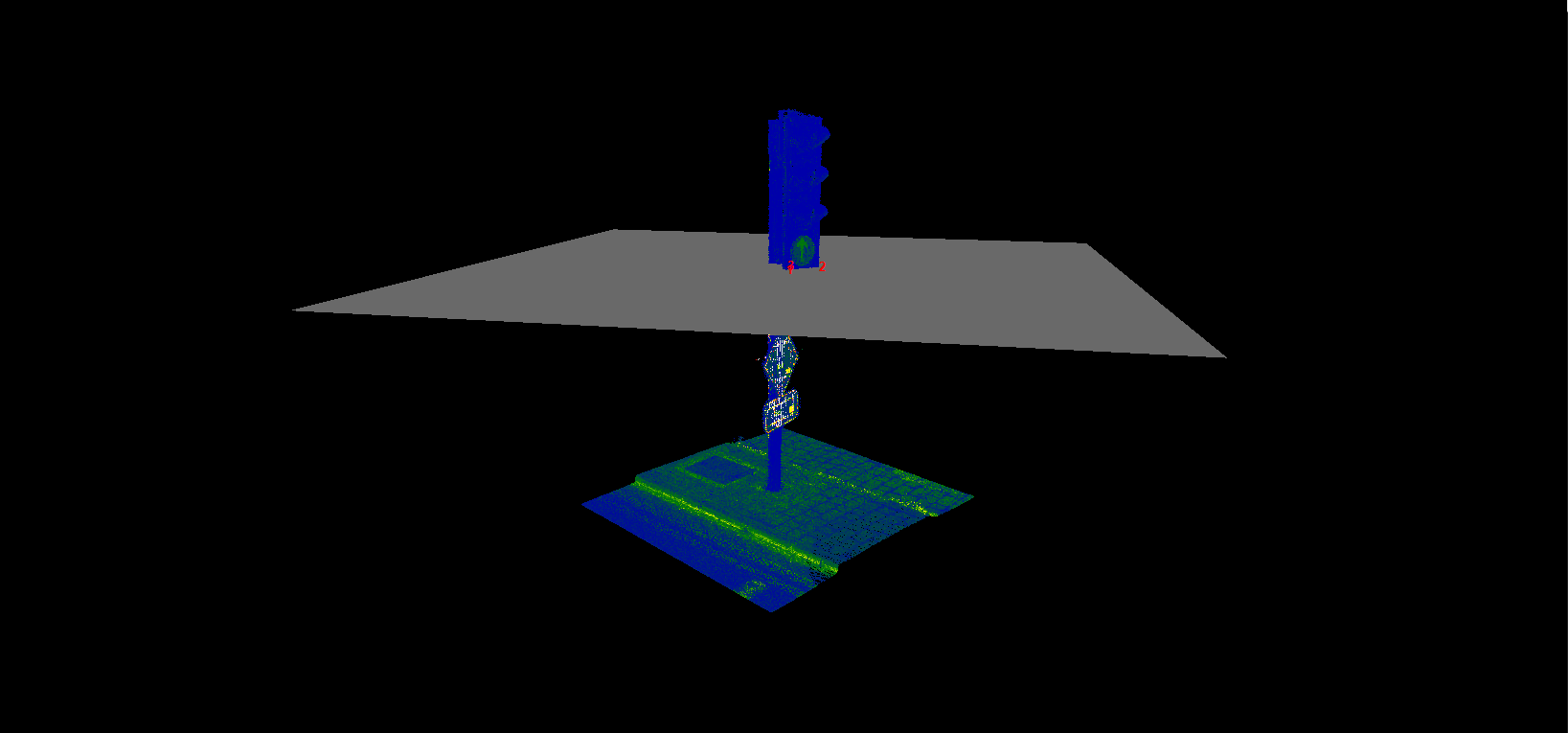
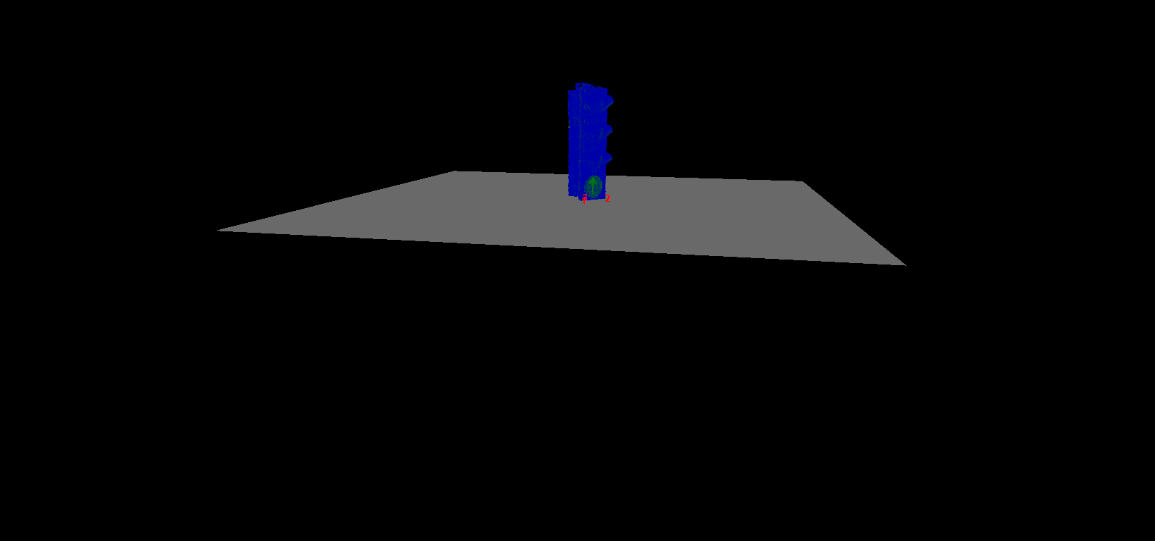
- Toggle Plane - Turn the auxiliary plane visualisation on and off with the plane. The auxiliary plane by default is not in view, the plane shall be moved to see the grid or the plane. See the description below. The plane is infinite, but the visualisation is limited to the clip frame area.
- Hide items on/off - This tool allows the users to hide the point cloud based on the slice mode selectors. The setting can be plane or slices. The tool can be used if the plane is turned on or off. This tool can hide a part of the point cloud based on the auxiliary plane location and user needs.
If the slice mode is set to slice, only a given slice will be visualised.

- Hide mode - Plane - Slice - The selector for the hide on/off function as described above. The default selection is plane.
- Move cutting plane/slice - This tool will allow the user to move up or down the reference plane (up and down are understood in the auxiliary plane's coordinate system) with the set value. Positive values will move the plane upwards, and negative values will move downwards.
- Cutting slice thickness - This setting will allow the user to adjust the slice thickness by entering the designated value.
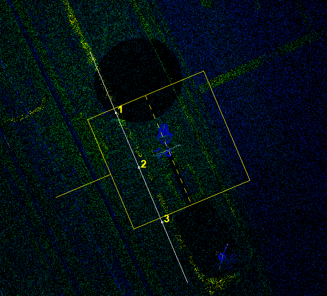
- Plane fitting - This tool allows the user to place the auxiliary plane in the given location. After starting the tool, the users can select point cloud or vector points. A minimum of 3 points shall be chosen, but more can also be selected. After pressing the enter, the tool will calculate the auxiliary plane. If only 3 points are selected, the plane will be placed instantly. If more than 3 points are selected, the software will calculate the plane with the best fitting method and provide information for the user about the plane. The plane can be placed with any 3 points to be non-horizontal and non-vertical.

- Plane fitting (least square) - Same as plane fitting, but the plane calculation will use the least square method.
- Plane Dropdown - Further plane definition pre-set options are available under this menu.
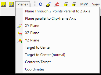
The description of the points is the following:
Plane Through 2 Points Parallel to Z Axis - This tool will make the auxiliary plane parallel with the Z axis using the 1st and 3rd plane points.
Plane parallel to Clip-frame Axis - The auxiliary plane will be aligned with the clip-frame axis.
XY/XZ/YZ Plane - Presets for auxiliary planes related to the global coordinate systems.
Target to Center - Set the target point to the centre of the auxiliary plane. The centre point has been calculated as the centre of the three defining points.
Target to Center (normal) - Same as above, and the 3D view camera will be aligned with the normal of the centre point.
Center to Target - The centre point of the auxiliary plane will be moved to the target point without modifying the plan's direction.
Coordinates - This tool will open the plane properties, where coordinates can specify the first, second and third points.
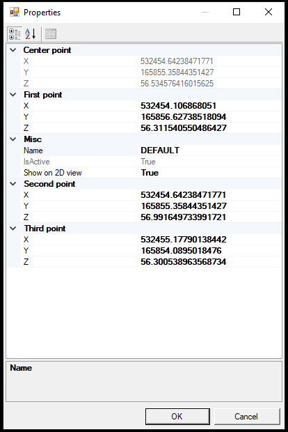
The user can enter the first second and third point coordinates, and the center point will be automatically calculated, it cannot be updated manually. If the Show on 2D view option is set to True, the auxiliary plane and the defining points will also be visible on the 2D view.