¶ Measure toolbar
The measure toolbar supports the user with measurement tools to measure distances and angles. Some other useful tools can be found in this toolbar as well. The measure toolbar becomes active if a cloud or vector is loaded into the project. The dimensions are in meters and decimal angles.
The description of the tools are the following:
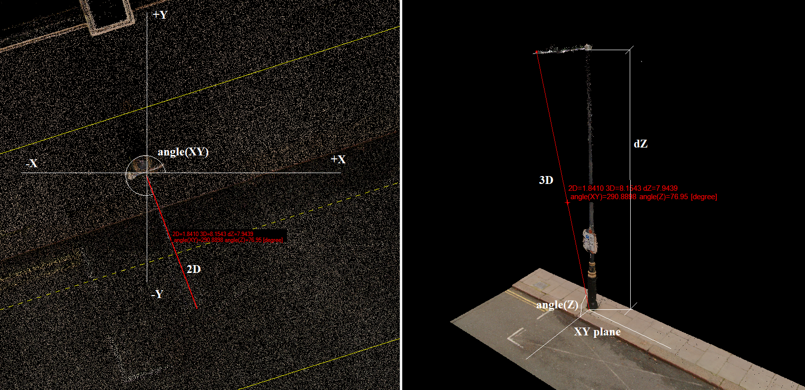
- Distance (2pt) - This tool allows the users to measure distance and angles between 2 points (point cloud or vector points). The tool supports all snap modes. The measure toolbar provides information inside a black frame. The understanding of the values is the following:
2D - 2D (planar) distance between the 2 points
3D - 3D (taking into account the elevation difference) distance between 2 points
dZ - The elevation difference between the 2 points
angle(XY) - The angle that can be found between the +X axis of the global coordinate system and the direction line between the 2 points. The angle is counted counter-clockwise. This information can be essential during CAD extractions.
angle(Z) - The angle between the horizontal plane and the direction line between the 2 points.
See example below:
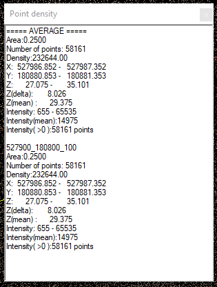
- Measure Density - The measure density tool allows users to measure the point cloud density and other attributes inside a specified area. After starting the tool, the settings panel will appear. The user can select the target classes, which shall be considered for the density filtering. The sample area can be a rectangle or a circle, or the software can inspect the whole area. The width value will set the rectangle size or the circle diameter.
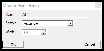
After pressing OK, the mouse cursor will turn to the selected shape (if not, the whole area option has been chosen for Sample), and this cursor will have the absolute size (if the user zooms in or out, the cursor will keep the set dimension). The user can click on the designated location with this cursor to get the result window with the calculated values. The software will calculate helpful information based on coordinates, intensity values, and based on tiles.
- Circle info - This tool allows the user to measure a cylindrical object's diameter based on the set parameters. The tool can utilize all snap modes. After starting the tool, the settings panel will appear, and the user can select objects in the views. We recommend using the 3D view as the support line can indicate instantly if the user has chosen what they want to pick.
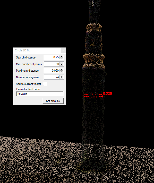
The settings panel allows the user to add the measured value to the current vector's diameter attribute. Suppose the checkbox is selected and the attribute value is set correctly; upon clicking a pole, a new vertex will be inserted into the designated location, and if the tool can append the diameter, it will perform this action automatically.
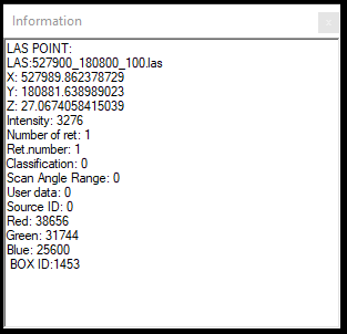
- Information - The information tool lets users get info about point cloud points. The tool supports all snap modes, but only the position coordinates will be returned if the point cloud snap mode is active. This function will not provide information about SHP attributes; for SHP info, use the Information tool on the Shape Toolbar. The information tool will provide all information from the selected cloud points, including all attributes stored inside the LAS file.
- Create Popup - The function will place a Measure menu on the top bar after the Help menu to access the tools from a menu until the software restarts.