¶ Extraction for CAD environments
The PCS software has been designed for mass extraction of vectors from point clouds and rasters, mainly for databases or SHP files, which makes the software more like a GIS tool than a CAD one. During the years of development, the need has arisen to support CAD extractions and to utilise the extracted vectors in CAD environments. This need has been addressed, and the software has been capable of extracting vectors into CAD environments since 2015.
The software cannot directly modify the DXF or DWG files. However, the user can snap to DXF/DWG vertices in 3D view-only, and visualisation works for both views. The extraction shall be performed in SHP files or FDB datasets. The software has carried out the transfer between the GIS and CAD fields based on a set of attributes defining the key parameters for the CAD counterpart of the SHP/FDB element. With this knowledge, the users can create templates within the attribute tables to extract vectors, which can be directly exported into a DXF/DWG file, allowing the export to CAD environments from PCS.
This method is a 2-way process, as PCS can export from SHP/FDB to DXF/DWG and import SHP from the DXF/DWG files. It is also possible to easily enhance existing datasets to export data into a CAD environment using PCS as a converter.
Please note that the software is limited to the standard CAD objects: points, polylines, polygons, texts, blocks and 3D faces. Other special CAD objects - used by one or more specific CAD applications or extensions - are not supported. Texts and multi-texts are supported. Blocks with attributes and dynamic blocks are also supported if the attribute name is not longer than ten characters (because of the limitation of the SHP attribute name length). PCS ignores hatches; they cannot currently be imported into SHP files.
This guide will cover the following use cases: extract from scratch into a CAD environment, enhance already existing datasets to export into CAD, CAD to PCS operations and usage of blocks with special attributes.
For this guide, the user shall be experienced in the basics of PCS. For new users, read this guide only after reading the Basic and the Advanced Extraction Guides.
¶ Extract in PCS for CAD environment from scratch
The extraction for the CAD environment works the same way as for working into SHP files - the user will extract the information into SHP files. Applying GIS logic to a CAD extraction required understanding the nature of the SHP files. As an SHP file can be a point, polyline or polygon, the representation of the CAD elements should be aligned with this. The polyline is the easiest, as it will result in a 3D polyline (not lines). Polygons from SHP will result in a closed polyline in CAD. Point SHP files can be of three types: point, block (or, as PCS calls them, Inserts) and texts. These objects will be stored in point SHP files, and the attribute layout is what can make the difference between them. To ensure an SHP can be exported into CAD, the respective attributes shall be created using the attribute table structure editor. ALL attributes shall be filled for a proper export.
IMPORTANT! - If the attributes are not filled or the mandatory attributes are partially filled, the export may crash or result in an unexpected output, or elements might be missing! Always crosscheck the attribute table before export, and make sure there is no empty attribute, where it shall be a value.
Luckily, there is no need to append the attributes manually. PCS can offer a quick assignment for the attributes so the SHP files can automatically receive the required attribute structure. For a better understanding, the attributes and possible values are explained here:
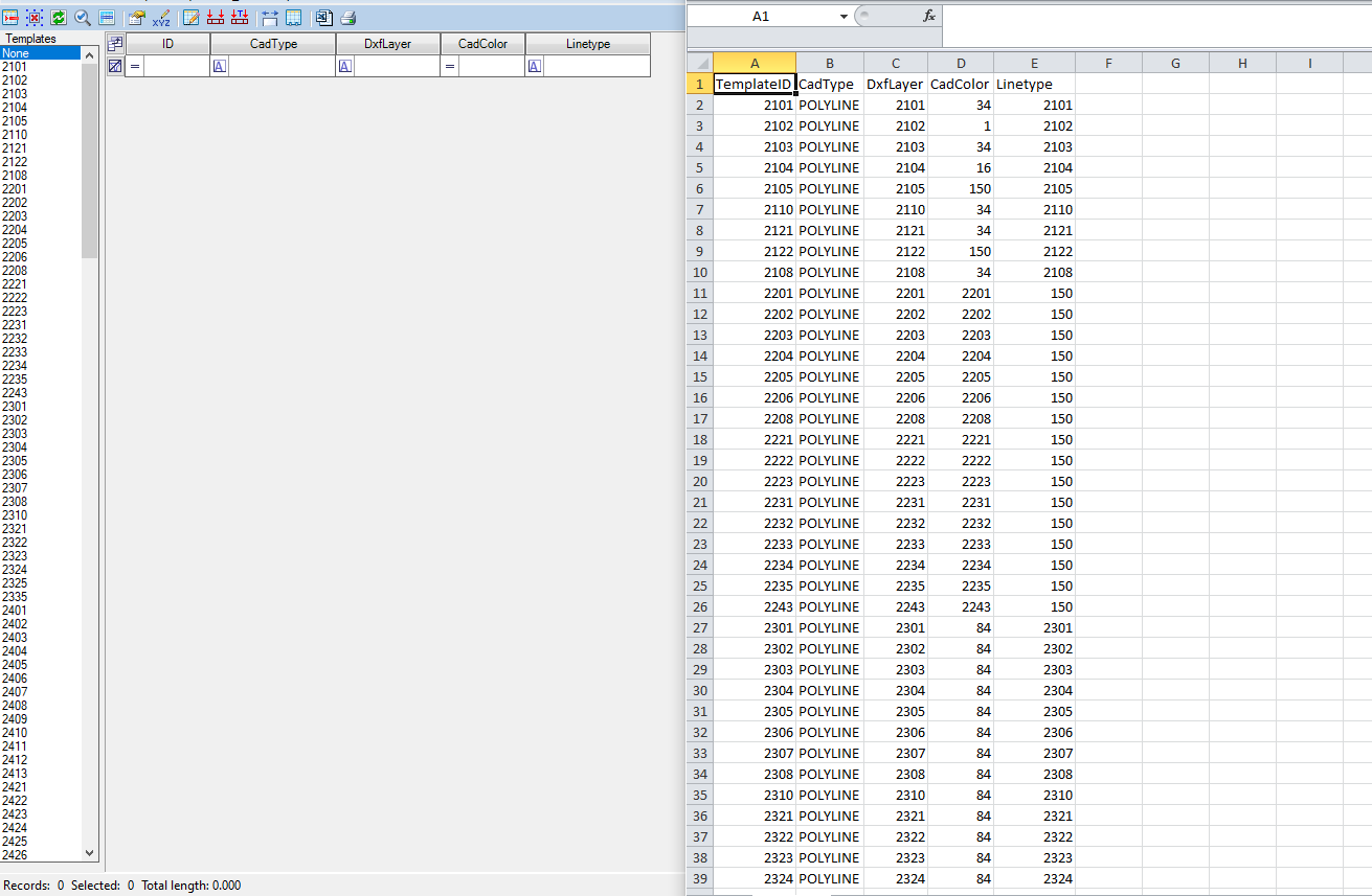
- Point SHP - Results in points in CAD
CadType - This defines the type of the export. The value always shall be "POINT".
DxfLayer - The target layer's name in CAD.
CadColor - The object's colour is based on the CAD colour chart; see below.
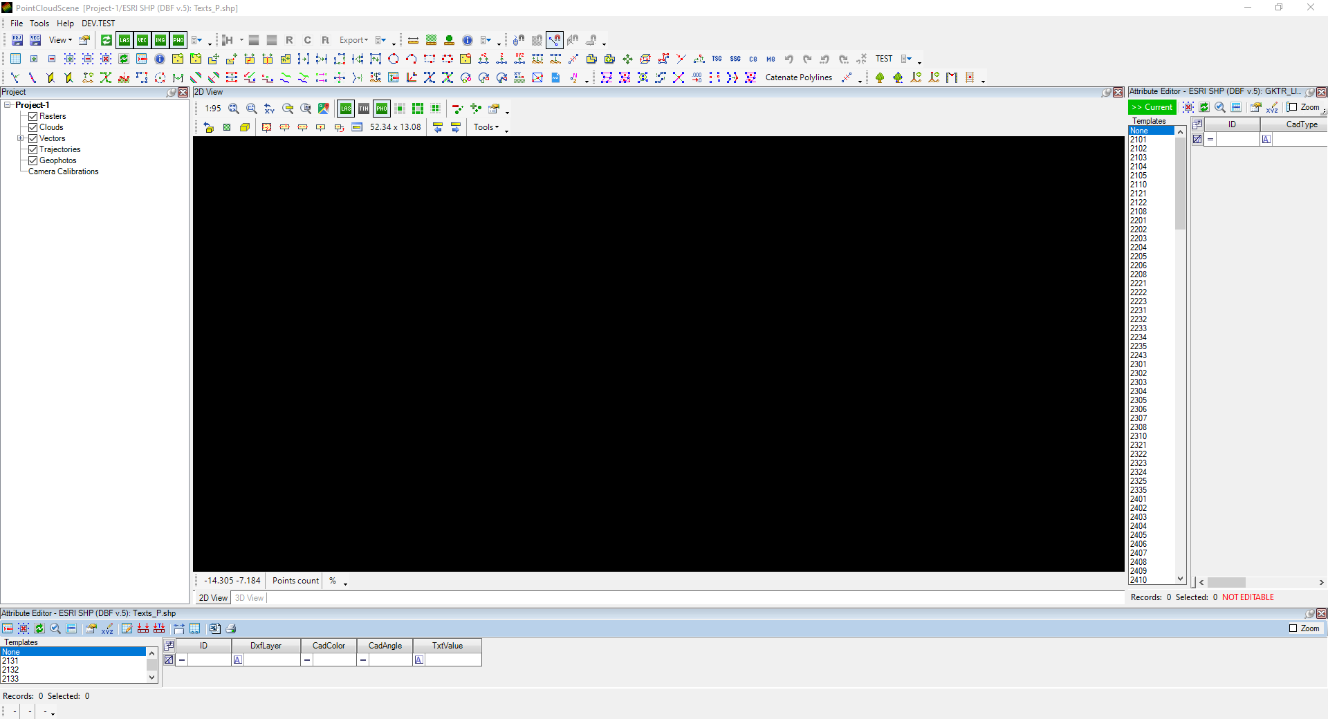
- Text SHP - Results in single-line text in CAD, with the option to flag the text
CADType - This defines the type of the export. The value shall be "TEXT" for single-line texts and “MTEXT” for multi-line texts.
DxfLayer - The target layer's name in CAD.
TxtValue - The text which needs to be displayed in CAD. Appending Text-type attributes into an SHP will automatically set this attribute as a label for PCS (if defined manually, the labelling shall be set from the properties). This field can be empty during the export, but the element will not be exported; no point or empty text will be placed. To enter multi-line text, right-click on the field and select the ‘Multi-line editor’, and enter the multi-line text.
CadColor - The object's colour is based on the CAD colour chart; see below.
CadAngle - The rotation of the text. The horizontal direction is 0°, and the rotation is counted counter-clockwise. Use the Distance (2pt) tool to understand the XY rotation angles from the Measure Toolbar, or to set the rotation of the text quickly, use the Rotate Point tool from the Shape Toolbar 2. The default value is 0.00.
Style - The assigned style for the text. Use the respective style; if not defined, enter "STANDARD". This field cannot be empty.
Height - The text height in meter dimension. The default value is 0.00 but shall be updated; it cannot be left on the default value.
LeaderSide - None is the default value, where no leader is being used. Select Left or Right for the respective leader side.
LeaderDX - The offset for the leader for the X axis.
LeaderDY - The offset for the leader for the Y axis.
- Insert SHP - Results in blocks in CAD
CadType - This defines the type of the export. The value always shall be "INSERT".
DxfLayer - The target layer's name in CAD.
RefName - The block name in CAD is based on the seed file. The seed description can be read below. The block display setting is also described below.
CadColor - The object's colour is based on the CAD colour chart; see below.
CadAngle - The rotation of the block. The horizontal direction is 0°, and the rotation is counted counter-clockwise. Use the Distance (2pt) tool to understand the XY rotation angles from the Measure Toolbar, or to set the rotation of the block quickly, use the Rotate Point tool from the Shape Toolbar 2. The default value is 0.00.
ScaleX - The scale factor of the X dimension for the blocks. By default, it shall be set to 1, but the default value is 0.00; make sure the correct value has been set.
ScaleY - The scale factor of the Y dimension for the blocks. By default, it shall be set to 1, but the default value is 0.00; make sure the correct value has been set.
ScaleZ - The scale factor of the Z dimension for the blocks. By default, it shall be set to 1, but the default value is 0.00; make sure the correct value has been set.
- Polyline SHP - Results in polylines in CAD
CadType - This defines the type of the export. The value always shall be "POLYLINE".
DxfLayer - The target layer's name in CAD.
CadColor - The object's colour is based on the CAD colour chart; see below.
Linetype - The line type of the CAD object after export. It cannot be empty. If the line type is unknown or not specified by the user, use the "Continuous" value.
PCS will define the attributes mentioned above for a polyline, but further attributes can be created manually to enhance the functionality of a polyline. PCS can handle text attributes during export from a polyline, resulting in an appended text at the centre point of the polyline mass if the attributes are correctly set.
TxtValue - The text which needs to be displayed in CAD. It can be an empty field. If it's used, it is recommended to set the Automatic Label inside the Properties of the SHP to the TxtValue field to display the text in 2D. This field for Polylines does not support multi-line text.
Style - The assigned style for the text. Use the respective style; if not defined, enter "STANDARD". This field can be empty for polyline SHPs.
Height - The text height in meter dimension. The default value is 0.00, and if the text attributes are used, it shall be updated, but if not, it can be left at 0.00.
- Polygon SHP - Results in closed polylines in CAD
CadType - This defines the type of the export. The value always shall be "POLYLINE" as the result is a closed polyline.
DxfLayer - The target layer's name in CAD.
CadColor - The object's colour is based on the CAD colour chart; see below.
Linetype - The line type of the CAD object after export. It cannot be empty. If the line type is unknown or not specified by the user, use the "Continuous" value.
PCS will define the attributes mentioned above for a polygon, but further attributes can be created manually to enhance its functionality. PCS can handle text attributes during export from a polygon, resulting in an appended text at the centre point of the polygon mass if the attributes are correctly set.
TxtValue - The text which needs to be displayed in CAD. It can be an empty field. If it's used, it is recommended to set the Automatic Label inside the Properties of the SHP to the TxtValue field to display the text in 2D.
Style - The assigned style for the text. Use the respective style; if not defined, enter "STANDARD". This field can be empty for polygon SHPs.
Height - The text height in meter dimension. The default value is 0.00, and if the text attributes are used, it shall be updated, but if not, it can be left at 0.00.
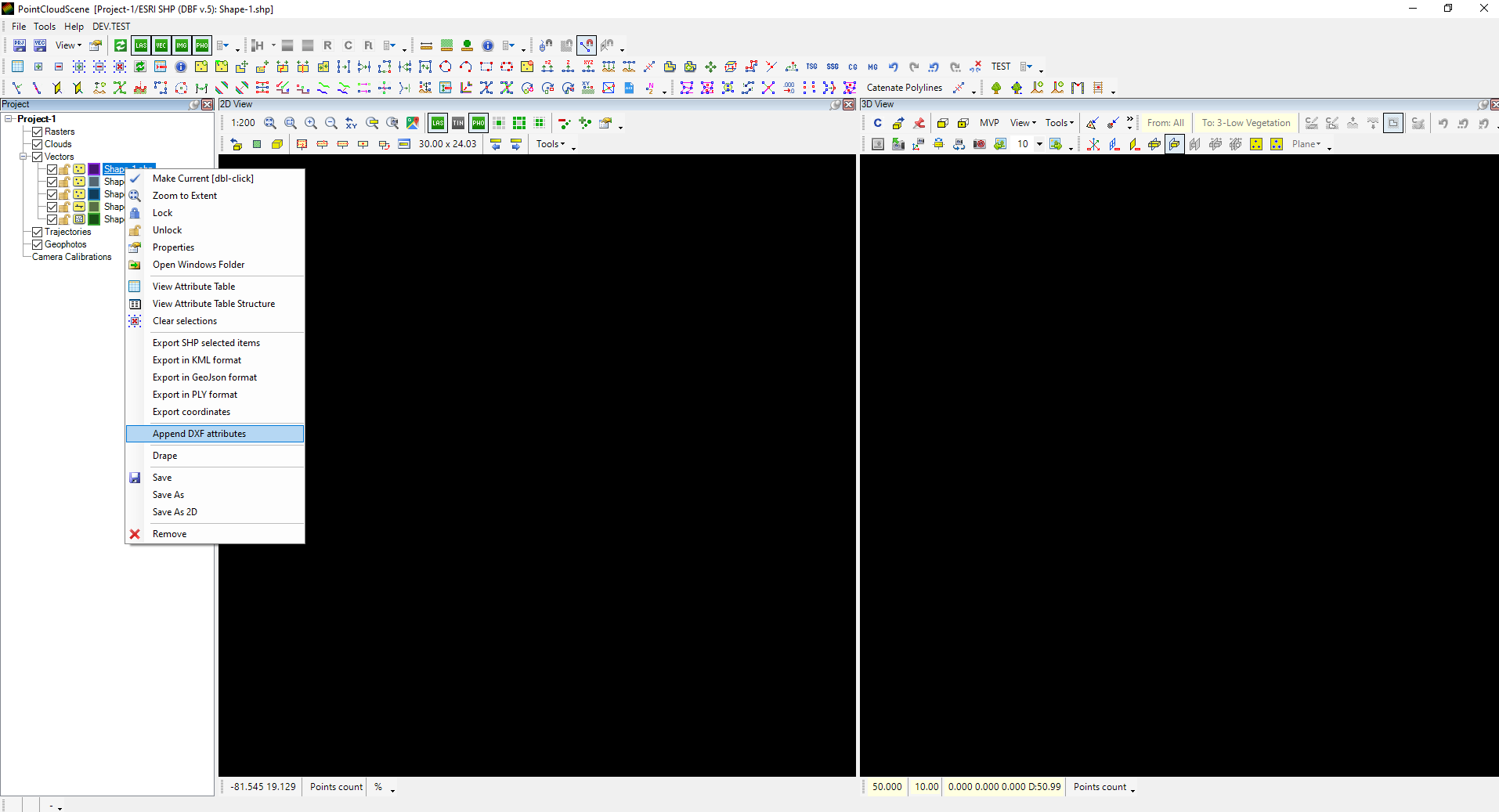
The respective attributes can be appended to an empty SHP by right-clicking on the SHP file and selecting Append Dxf Attributes. If a point SHP is selected, the software will prompt the user if the point, text or block attributes shall be appended to the SHP.
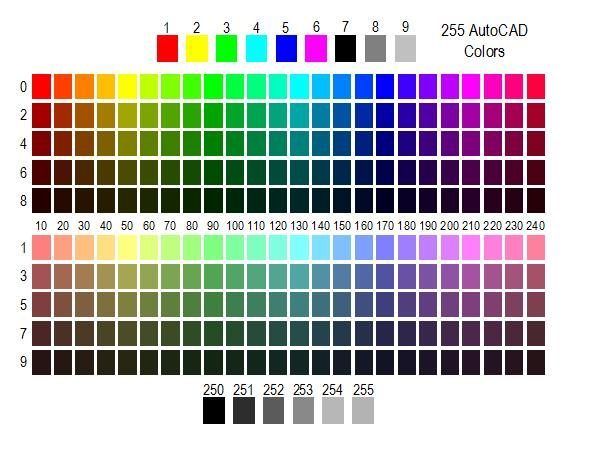
As mentioned above, the CadColor attribute can be assigned based on the CAD colour chart. This can be between 0 and 255; see the chart below.
If a CAD colour is specified in RGB colours, it is impossible to represent it within PCS, but if the seed file contains the layer, the By Layer colour can be applied during export.
The seed file has been mentioned multiple times; let's also explain this. The seed file is used during the export to convert the SHP files into DXF/DWG based on the seed file. The seed file shall contain all layers, styles and block definitions used inside PCS, so during the export, the converter will have an "example" of how the output file will look. It is possible to export without a seed file, but the result will not contain any blocks; the styles and colours might be the default, so it is always recommended to use a seed file. In general cases, the seed file shall be empty, as the content of the seed file will be transferred to the output file. In some exceptional cases, this can be useful when the user wants to append some content to an existing drawing, but it is strongly recommended to keep the seed empty. The software also supports DXF and DWG files as seed, but the version cannot be newer than 2013. The software will ignore the seed if a newer version of the DXF/DWG file is being used as a seed. It is highly recommended that all seed files be in a fixed location, and if the user works in an organisation, everyone within the organisation has the seed files in the same place. Commonly, the C:\PCS folder can be used for this purpose.
After the SHP files are created, save them. Before continuing the work, the block SHP requires an additional adjustment, as by default, the SHP cannot display the blocks in PCS.
¶ For older PCS versions (2024.06.13 or earlier)
The seed file path shall be set inside the SHP's DPRM file to display the blocks. Remove the SHP from the project before adjusting the DPRM file. Open the block's DPRM file in Notepad, and make sure that the <SymbolLibrary> field contains the full file path for the seed file. Also, adjust the <RotationColumnName> field to 'CadAngle' and the <SymbolNameColumnName> field to ‘RefName’.
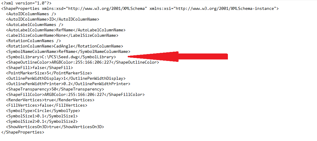
Don't forget to save the changes to the DPRM file. After loading the SHP in PCS and placing a point where the RefName has been set to a block name, which can be found inside the seed file, the block will be displayed. If the RefName attribute does not match any block definition from the seed file or the seed file is saved in a newer DXF/DWG version 2013, the block will not display. The point will be there but won't be visible in 3D; in 2D, only the point will be visible.
¶ For newer PCS versions (2024.06.25 or newer)
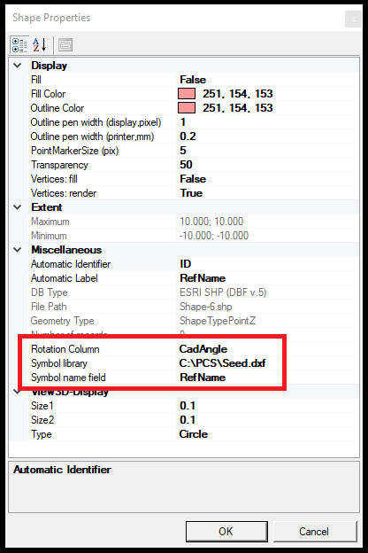
Open the block SHP file's properties and assign the Rotation Column to CadAngle, the Symbol Name Column to RefName, and assign the full file path - including file name - referring to the seed file. This will allow PCS to visualise the blocks properly including rotation. After the settings are made, the SHP file shall be saved and re-opened for the changes to take effect.
In case the block does not have a respective definition in the CAD file, or it is assembled from elements that PCS cannot display, the block will be displayed with a square with an X in 2D and a red circle in 3D. If that happens, please try the export to see if PCS cannot display the block or the RefName has a typo. These blocks are still functional; the user can snap them, but if the block definition does not exist in the seed file, a single point will be exported.

Now everything is ready from the technical side to extract for a CAD environment. The next step is not mandatory, but it is highly recommended that templates be set up for each SHP file, as without templates, too many attributes will be filled out, and this would set back productivity. If a few templates are used, the user can create those manually. Still, suppose a lot of layers are used; it is recommended to organise an Excel sheet with the designated attributes, finalise the templates in the sheet, and import a CSV, which has a matching attribute structure (including template names) with the SHP so that it can be imported into the SHP file with a few clicks. The template batch import from CSV does not support multi-line texts, the user shall update TEXT values to MTEXT if needed including the pre-set values.
Please note that the Excel file should have a header that matches the attribute table structure. See the Templates article for more info. If the templates are defined, it is recommended that the attribute tables be docked somewhere around the 2D or 3D window to make sure the templates are visible and the user can change the templates quickly during extraction. The best practice is to dock it to the sides if an attribute table is essential only for the templates and no manual attribute modification is needed. If the attributes are adjusted manually, it is recommended that the window be docked to the bottom part of the screen. In this case, it is best to be arranged to 2 displays or as tabbed. Read more about docking here.
If everything has been appropriately set, the user will see the linework displayed with the CAD colours, and the block representations will also appear. The extraction shall be done as usual using the templates.
When the extraction is ready, the user can export the final drawing.
IMPORTANT! - ALWAYS MAKE SURE ALL ATTRIBUTES ARE SET! Wrong or missing attribute settings might corrupt the export or result in missing elements in your DXF/DWG file.
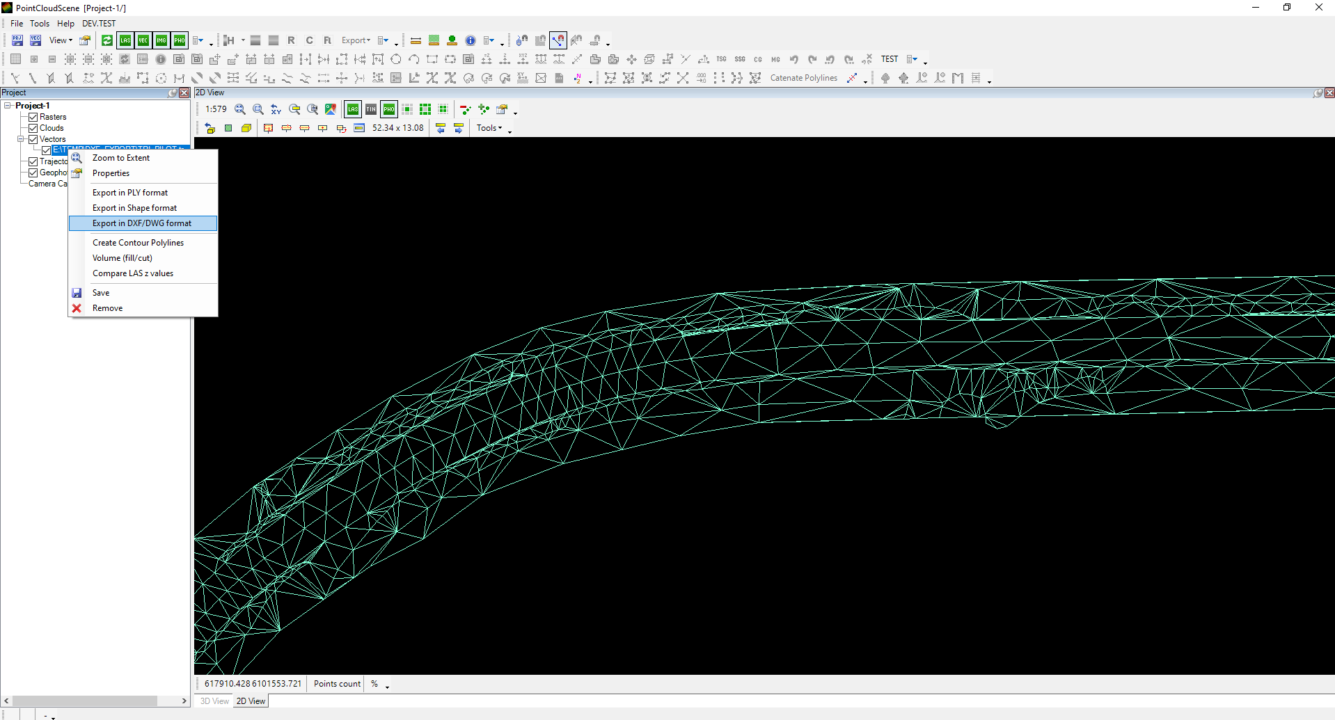
The export can be initiated by right-clicking on the Vectors inside Project Explorer and selecting the Export FDB/SHP/TRI to CAD. Please note that the export can be initiated only from this point; if the user right-clicks single SHP files or folders (if group by folder is active), this option will not be available. After starting the tool, the following control panel will appear (the content of the panel might vary depending on the license type):
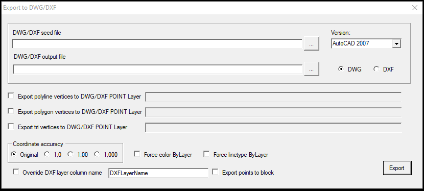
The description of the window tools are the following:
- DWG/DXF seed file - The user shall browse the seed file here, containing all layers and block definitions used during the export. It is possible to export without the seed file, but blocks will be exported without definition, and the layers will not receive the colour information. The seed file - by default - shall be empty. If it is not, all content from the seed file will be included in the output file as well. The seed file can be DXF or DWG as well. If one format is not visible in the browse window, copy the full file path to the file name or type*.dwg to the filename and press enter, and the browse window will display the files.
- DWG/DXF output file - The output location of the exported file. The output file can also be DXF or DWG; use the respective extension in the file name.
- Version - Select the output file version
- DWG/DXF - Select the output file type
- Export polyline/polygon vertices to DWG/DXF POINT Layer - The software allows the users to generate vertexes for all polyline/polygon object's vertices as points and export them to the specified layer by the user. Select the respective checkbox and fill in the Layer name if needed.
- Export tri vertices to DWG/DXF POINT Layer - The software allows the users to generate vertexes for all TRI triangle vertices as points and export them to the specified layer by the user.
- Force color ByLayer - This setting will force the ByLayer option for objects during export. As the CadColor attribute is numerical, it is impossible to append a "ByLayer" value. The layer's ByLayer colour will be used if the seed contains a layer with a different colour than the CadColor attribute. If no seed is used, the elements will appear white.
- Force linetype ByLayer - This setting will force the ByLayer option for objects during export for line types.
- Coordinate accuracy - Set the rounding during the export. The original coordinate accuracy is understood up to 4 digits.
- Export - Perform the export. If the export is done, the software will inform the user. The software will inform the user if there are errors in the dataset. The most common issue is that the attributes are not filled correctly or the seed file's version is newer than 2013.
After the export, the created file can be used in CAD. It is highly recommended to crosscheck the generated file; if everything is exported as expected, all blocks appear (eg. no missing block definition in the seed), and every colour and setting is good. The user can work with the drawing in the CAD environment if everything is set.
From version 2024.10.02, the triangles (TRI) can be exported using this panel as well. The TRI file cannot store attributes, so PCS will automatically assign those, and the exported triangles will be 3D faces in CAD environment.
Please note that the TRI files generated with PCS can be exported outside this tool as well. If a TRI is generated, the software can export the triangles into a DXF file by right-clicking the active TRI file and selecting Export in DXF/DWG file. The output file will contain all triangles at Layer 0. PCS currently does not offer any adjustments in the TRI output, as attributes cannot be assigned to the TRI file.
¶ Enhance existing SHP files to be used in the CAD environment
Enhancing existing SHP files to be exported to CAD is also possible. For example, a field survey - imported to an SHP based on the coordinate list - or country borders from a public database or measured data with a GIS data collector.
In our example, the district boundaries of Budapest will be used, and which dataset is publicly available.
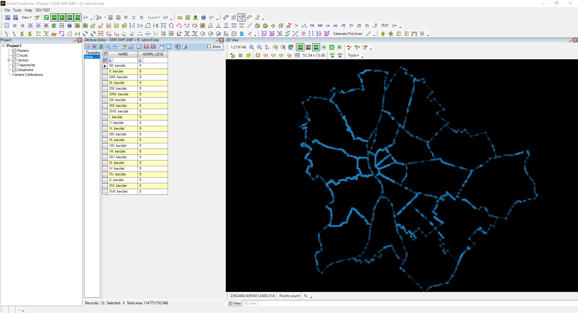
To be able to adjust content, the first thing is to append the DXF attributes for the SHP file as described above. If a point SHP is enhanced, the user shall consider whether the points shall be exported as points, texts, or blocks. Take into account the seed file requirement when the attributes are filled.
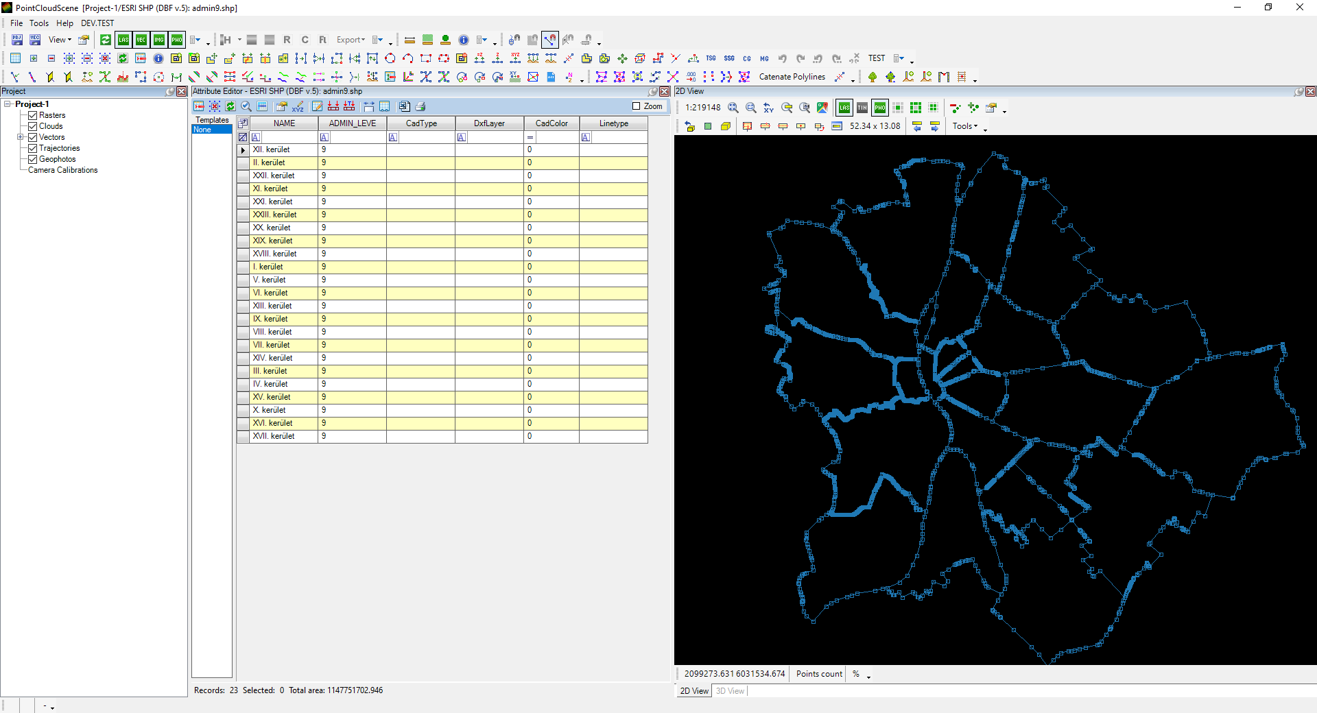
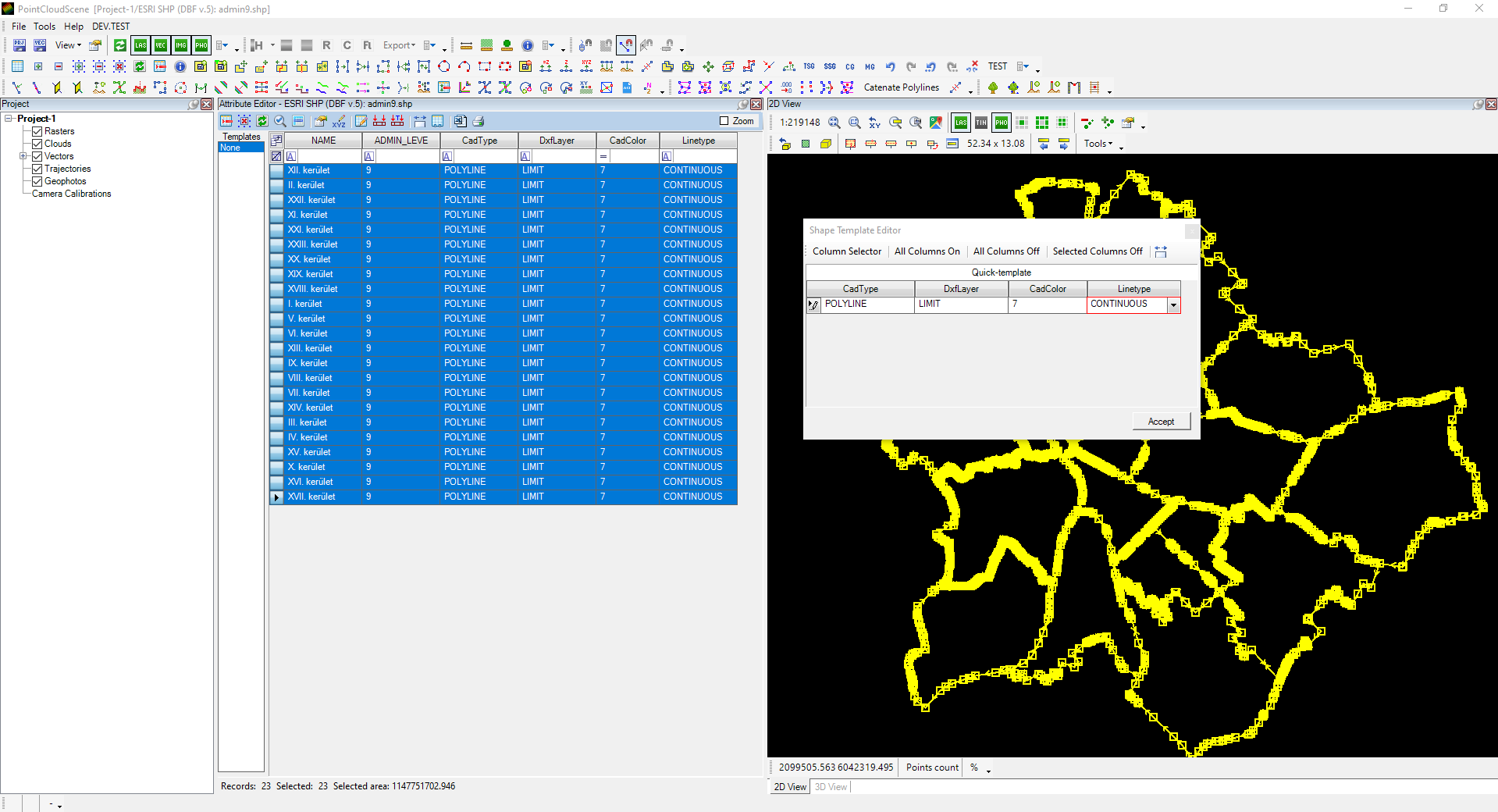
The user can now append the designed attributes for all or the selected records using the Apply Quick Template from the toolbar, or Templates can be defined and the Apply Template to the selected records. Please check the attribute table article for more info about the Apply Quick Template and Apply Template functions.
If the attributes are set, the export works the way described above.
¶ CAD to PCS operations
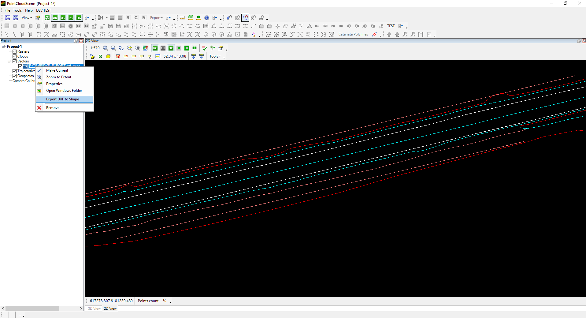
As described before, PCS cannot work directly in DXF or DWG files, but it is possible to work with the dataset directly in PCS. The software can import the DXF/DWG file content into SHP files, which can be modified and then exported back to DXF/DWG if needed. The DXF/DWG file shall be opened/dragged and dropped into PCS. To start the conversion, right-click the active DXF/DWG file, and select the Export DXF to Shape option.
After the option is selected, the conversion panel will appear:
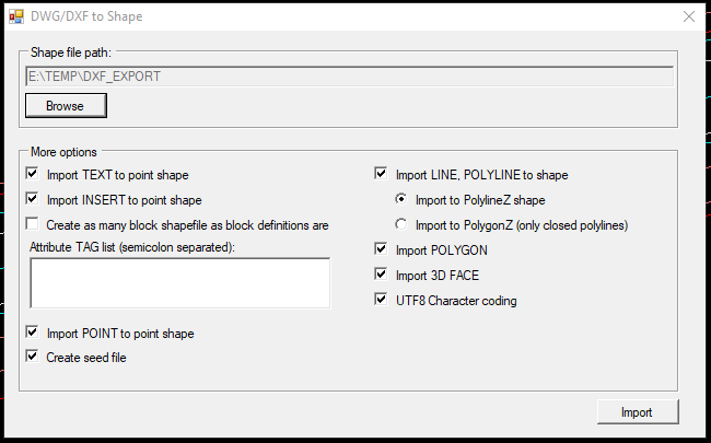
The setting definitions are the following:
- Shape file path - The imported files will be generated to the designated folder.
- Import TEXT to point shape - If selected, all texts will be imported into a new SHP file with TEXT attributes filled based on the DXF/DWG file. All text will be handled as single-line text.
- Import INSERT to point shape - If selected, all blocks will be imported into a new SHP file with INSERT attributes filled based on the DXF/DWG file. The created file will refer to the original file for block definitions. The blocks will no longer be visible if the original file has been moved or removed. Ensure the DPRM file path refers to an existing file as described above.
- Create as many block shapefile as block definitions are - If selected, the tool will generate separate SHP files with INSERT attributes filled based on the DXF/DWG file, as many separate blocks exist in the CAD file.
- Attribute TAG list (semicolon separated) - The user can specify block attributes that shall be imported from the DXF/DWG file if the blocks have attributes. The selected attributes will appear in the attribute table. The description can be read below.
- Import POINT to point shape - If selected, all points will be imported into a new SHP file with POINT attributes filled based on the DXF/DWG file.
- Create seed file - The software will generate an empty DXF seed file from the source file to be used as an empty seed. It will contain all layer and block definitions, just like the original file.
- Import LINE, POLYLINE to shape - If selected, all lines and polylines will be imported into a new SHP file with POLYLINE attributes filled based on the DXF/DWG file. Lines will be automatically converted to polylines, and the created SHP file will use 3D polylines by default (if the source lines or polylines were in 2D, the elevation value will be set to 0). The radio button allows users to select whether the closed polyline shall be imported into a polygon SHP separately.
- Import 3D FACE - If selected, all 3D faces will be imported into a new TRI file. The TRI does not contain attributes, which means that upon exporting the triangles again to DXF/DWG, all triangles will be exported to Layer 0, so all previous properties will be lost (like colour or display settings).
- UTF8 Character coding - This setting allows the import to understand special characters. If unchecked, the default character coding is applied, which is Windows (CR LF), which might distort the attribute values.
After the settings are set, press the Import button. The import will generate the files BUT WILL NOT OPEN AUTOMATICALLY IN PCS! After the import, the user shall open the SHP files (or the TRI). The files - including the seed - will have the same file name as the original file, but appendixes are applied.
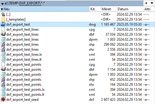
These SHP files can be opened in PCS, and the attributes are already filled based on the source DXF/DWG file. The blocks are also visible if blocks are imported. Suppose these SHP files are instantly exported back to DXF/DWG using the generated seed file; the generated file shall be identical to the source file (except if some special object is used, which PCS ignores during import). The imported SHP files can receive additional attributes and be enhanced in a GIS environment if required. The SHP files can be modified, or new elements can be created inside the SHP files and exported later. Creating templates is still recommended if the user works in an imported SHP file, so the attribute assignment is faster.
Since PCS version 2025.12.17, the software will generate an additional CSV file that provides an overview of the imported elements, what is imported and what is not. This can help debug the import process if some elements are missing.

¶ Usage of blocks with attributes
Blocks with attributes are standard in CAD environments, but using them in PCS and exporting them to CAD from PCS was implemented only at the beginning of 2024. One key factor for this conversion must be understood: only those attributes can be imported/appropriately exported between PCS-CAD environments with a shorter attribute name than ten characters, as the SHP attribute name cannot be longer than ten characters. If the user manages to import a longer attribute name into PCS, the software will automatically shorten the attribute name.
¶ From PCS to CAD
The general concept is that all attributes shall exist in PCS and the CAD block. The attributes shall be defined in the attribute table structure manager, and the values shall be set. The values can also be empty; the export of an attribute block will not be corrupted if more than the required attributes are present and if these are set to empty or null. The user can work with these SHP files to ensure all CAD-related attributes are set before initiating the export.
During the export, a seed file containing the block definitions shall be used, and those block definitions shall also include the designated attributes. If the attributes are in the SHP file, but the block definition does not contain them, the export will result in a standard block. If the SHP file contains more than the required attributes, and the block definition includes some of them, the export will result in a block containing only those attributes found in the block definition; the rest of the attributes will be ignored.
¶ From CAD to PCS
When the user tries to import a DXF/DWG file to PCS, the user shall specify the required attributes from blocks at the attribute tag list, separated with semicolons. The attributes specified here will be imported into PCS as attributes and can be updated if needed.