¶ Advanced extraction guide
The advanced extraction guide describes the extraction of vectors using attributes and templates. The use case for our extraction is the extraction of a small part of an urban street, where everything shall be extracted from fence to fence with attributes included. This guide will not describe the basics already described in the basic extraction guide, except if necessary.
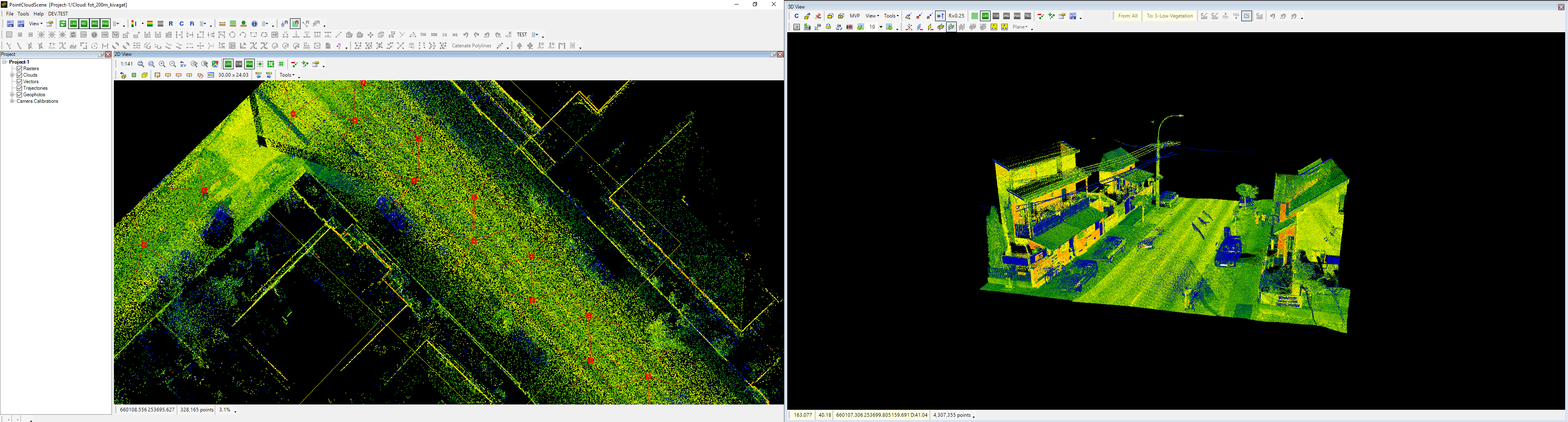
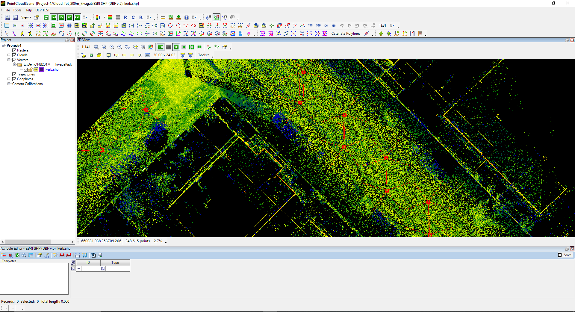
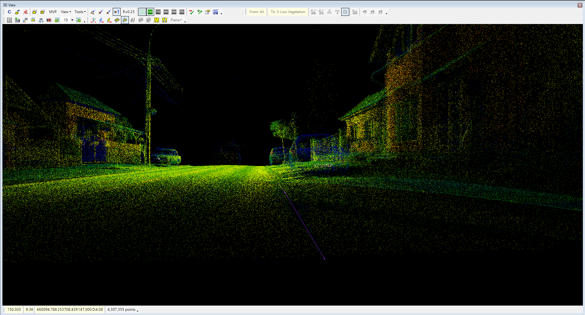
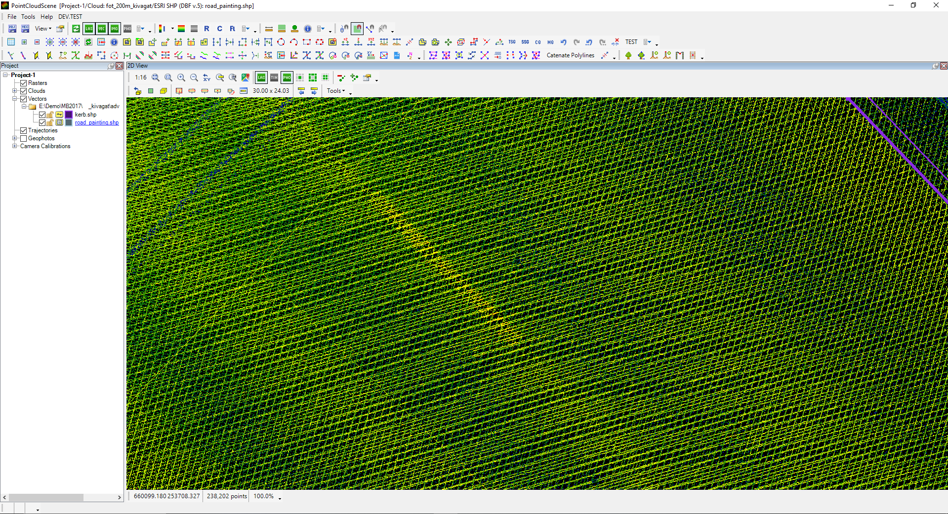
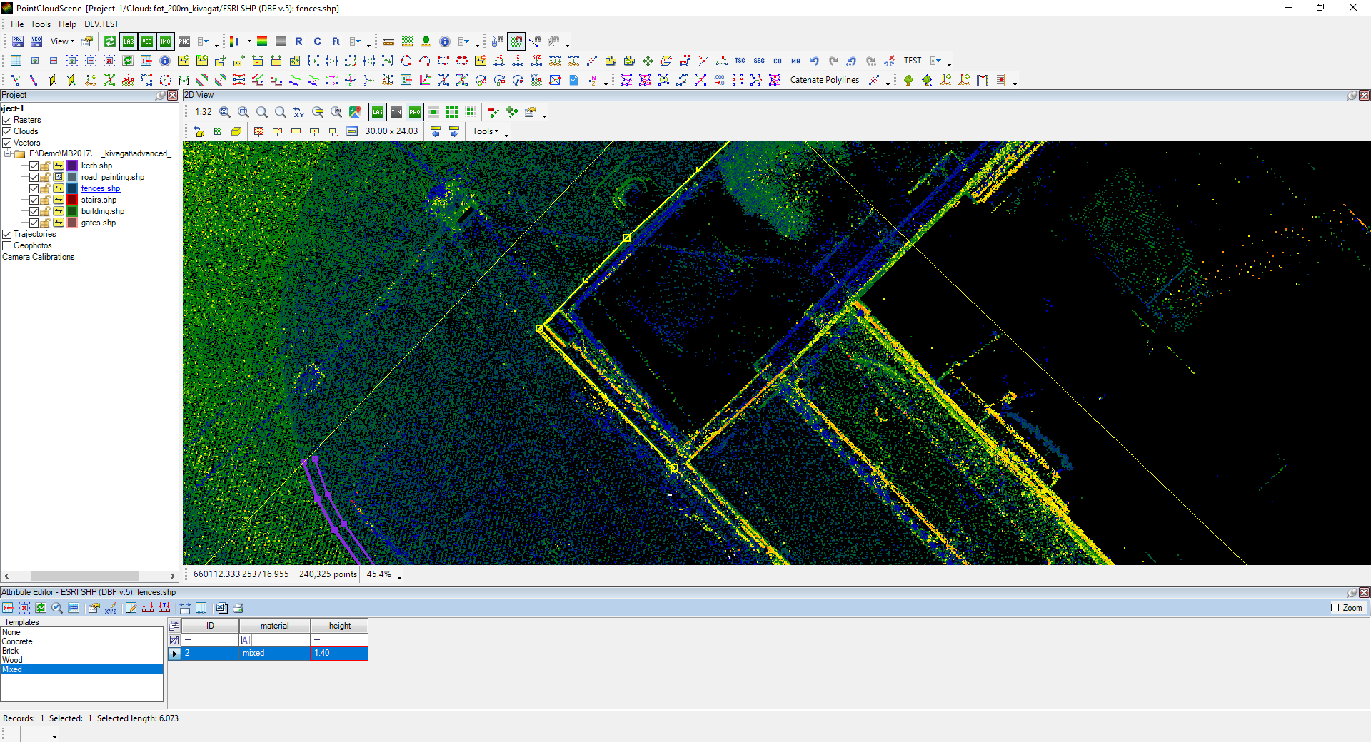
This guide will describe a 30 m-long area extraction for all possible methods to enhance the user's understanding of the tools and methods. The initial state is the cloud, and the respective geophotos are loaded into the project. For a better user experience, it is recommended to use a dual display so the 2D view and 3D view can be kept on separate screens, which will result in a more extensive working area. The colouring will be intensity-based with the default setting.
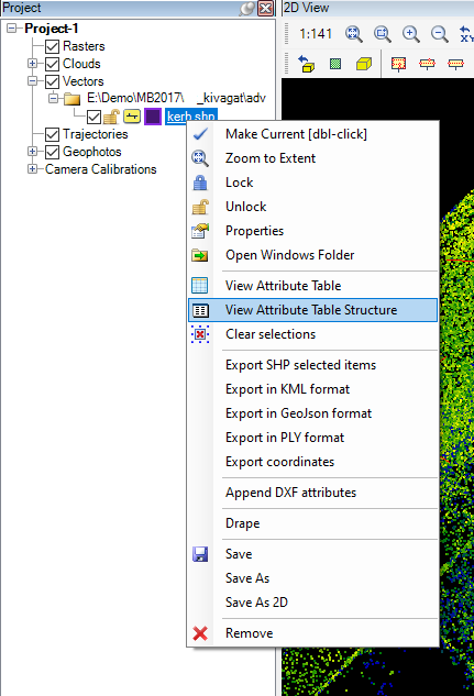
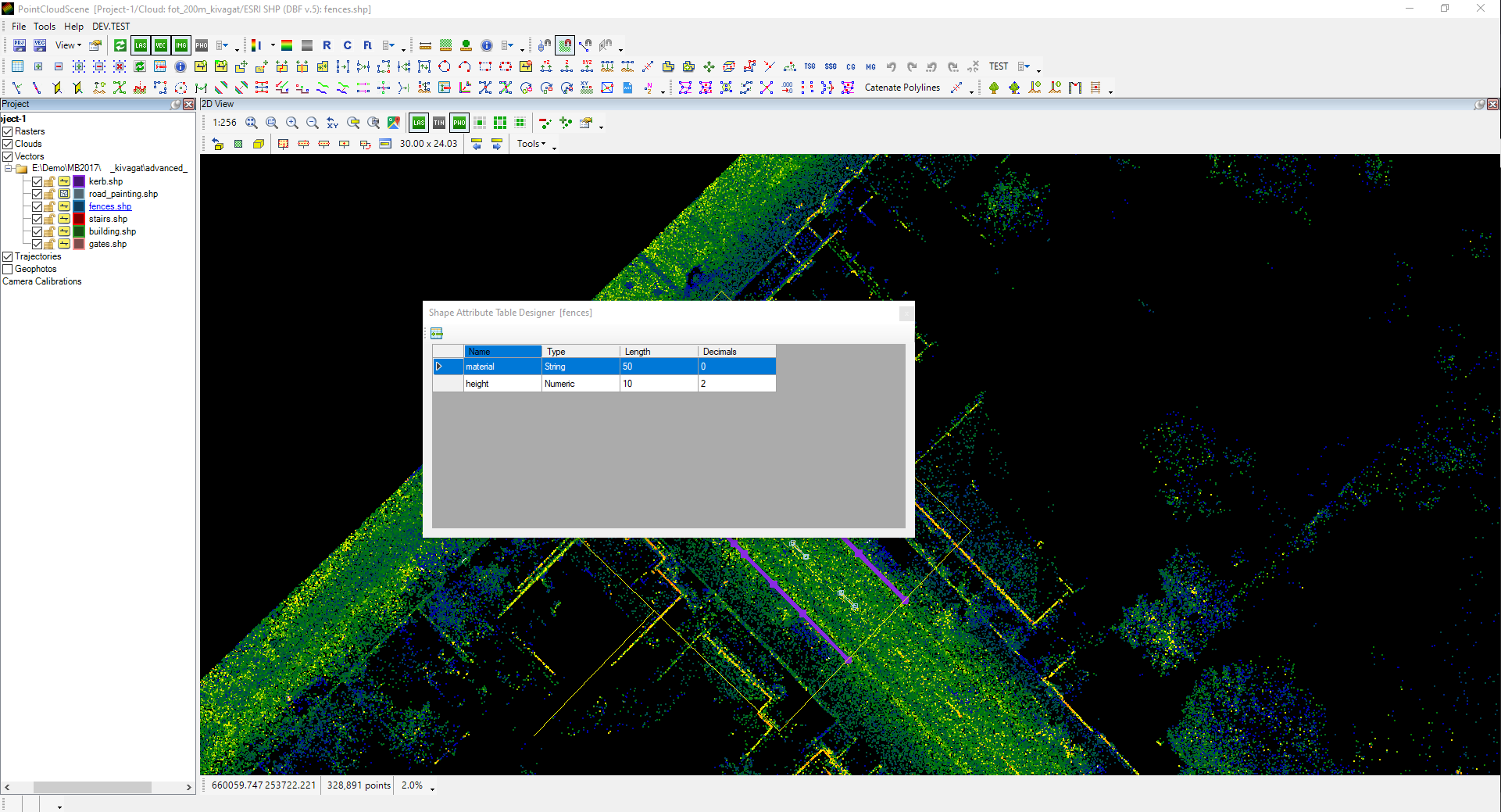
The SHP files will be defined along with the extraction, and attributes will also be stored. The first thing extracted is the edge of the road and the kerb. This is a prevalent task among the PCS users. For our example, a kerb polyline SHP is created. The attributes will be stored for these polylines so that the attributes will be defined inside the attribute table. Right-click on the SHP and select View Attribute Table Structure. Please note that this option is only visible for active SHP's.
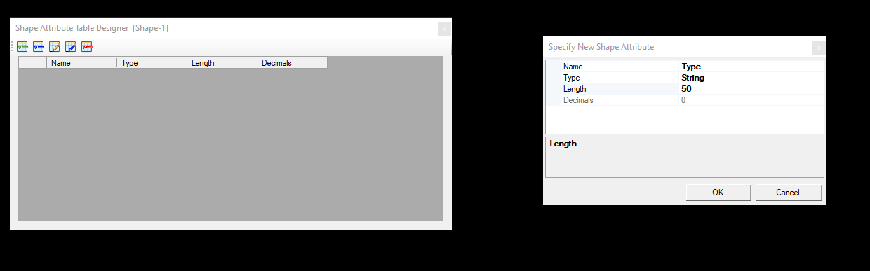
After the attribute table designer opens, select the Add New Field button and specify the attribute name, type and length. The attributes can be renamed, modified or removed using the tools in the designer window.
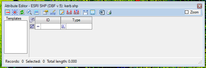
The attribute table can be docked to one of the views, and it is recommended to use docked windows for a better workspace arrangement.
As the attribute table is ready, the extraction can be started. As it is required to store attributes, two approaches are possible:
- Approach - Extract the vectors and fill in the attributes - The attributes are empty by default as a record is created.
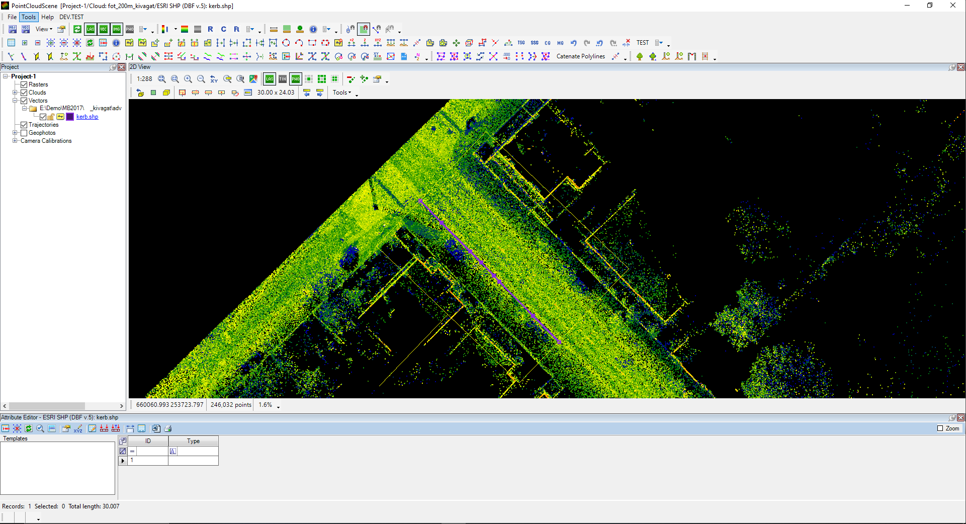
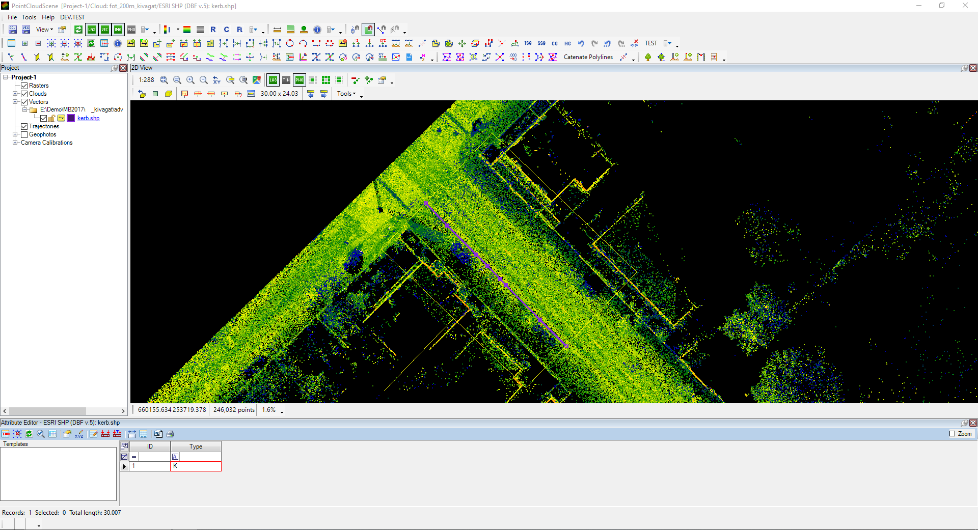
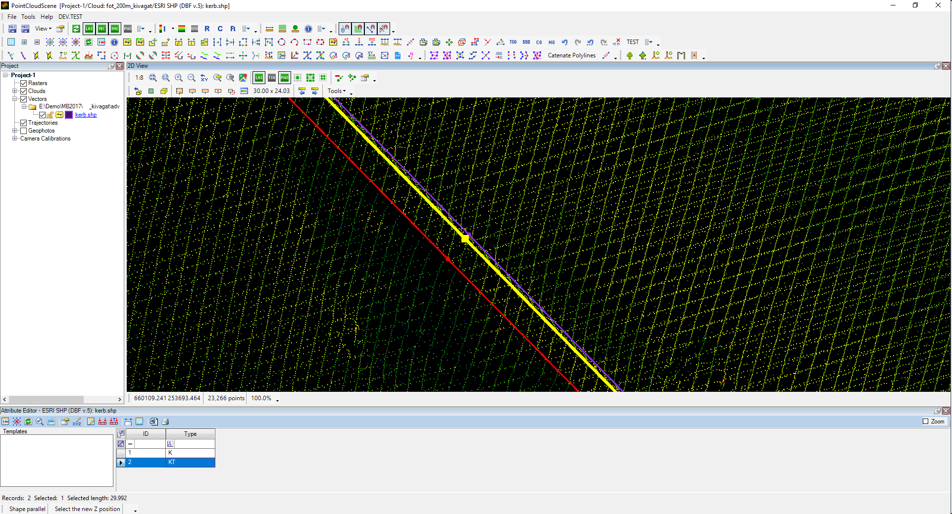
Start the New Element tool from the Shape Toolbar, set the snap mode to free point snap only, and extract the kerb's edge at the intersection with the asphalt in 2D view.
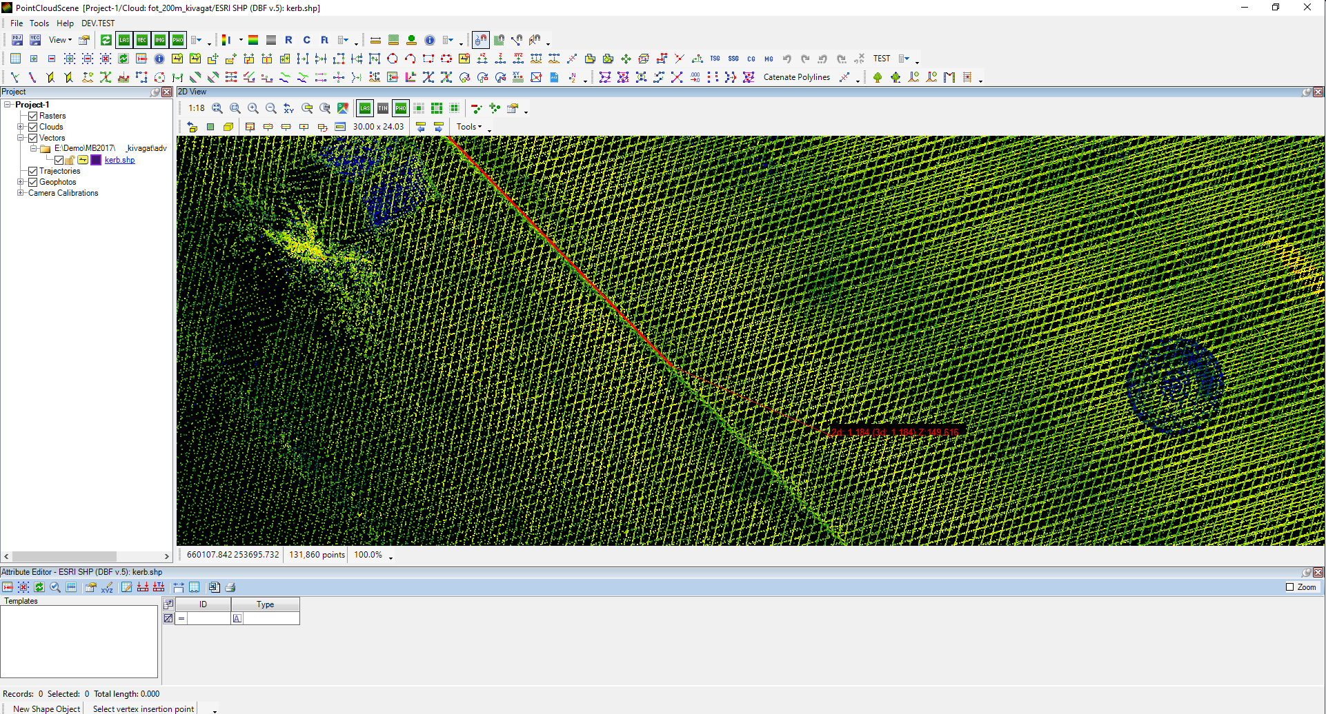
After the line has been drawn, press enter to accept the temporary line. This will create the record in the attribute table, and all attributes will be empty.
As the line is created in 2D view using free point snap, the elevation shall be adjusted or cross-checked in 3D view. The Drape or Modify Vertex Z functions can be used from the Shape Toolbar. Please check the Draping article for a better understanding of the drape logic.
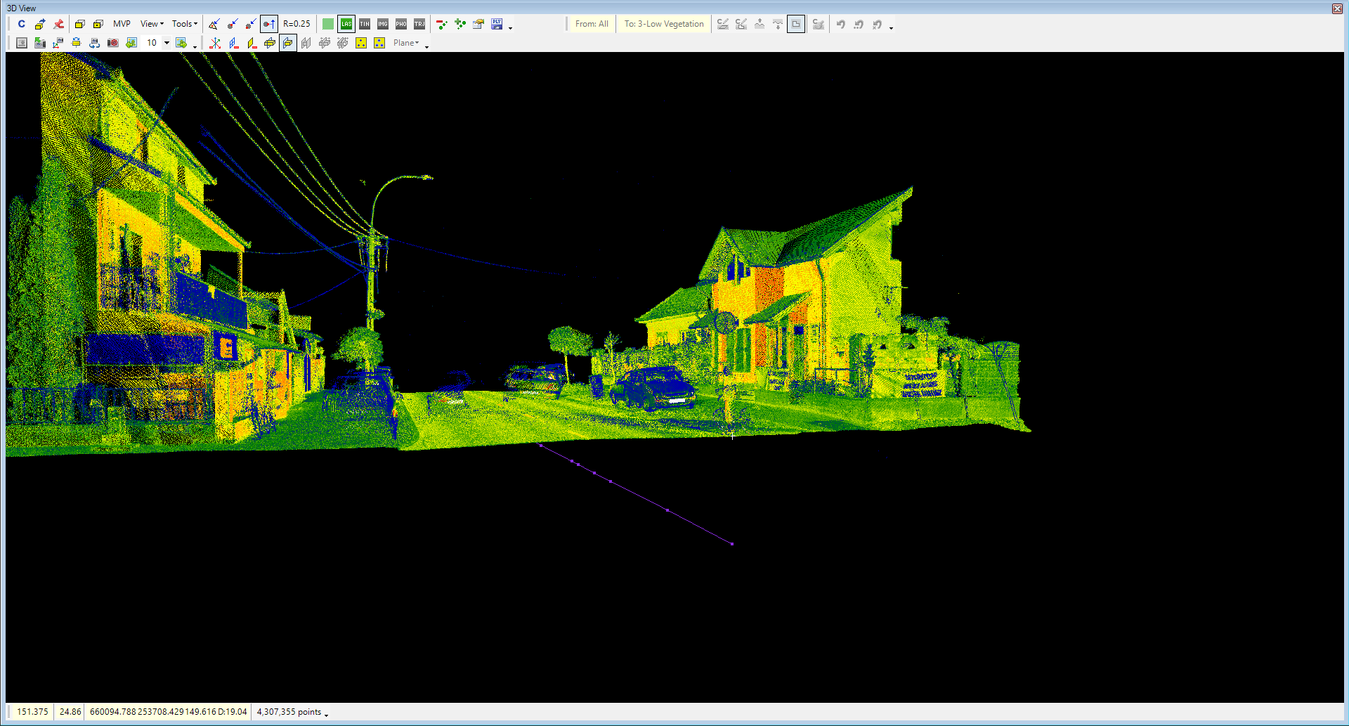
IMPORTANT! - It is always advised to cross-check the elevation after draping to make sure the drape resulted in the designated output, as the point clouds might contain noise or false points, which might mislead the drape, or the drape radius was not selected appropriately for the situation.
After the line is aligned in 3D, the attributes shall also be filled. The Type attribute has been created before. For the kerbs, the following attributes will be used: K (kerb), KT (kerb top), and KB (kerb back). The K attribute will be appended to the record. Click inside the field, enter the designated value, and press enter. Please remember that the attribute type can affect what can be entered into the field. For example, letters cannot be used for a numeric field.
After the first line is fixed, the other two kerb lines shall be extracted. The same extraction method can be used for the following line, but another approach will be presented for presentation purposes.
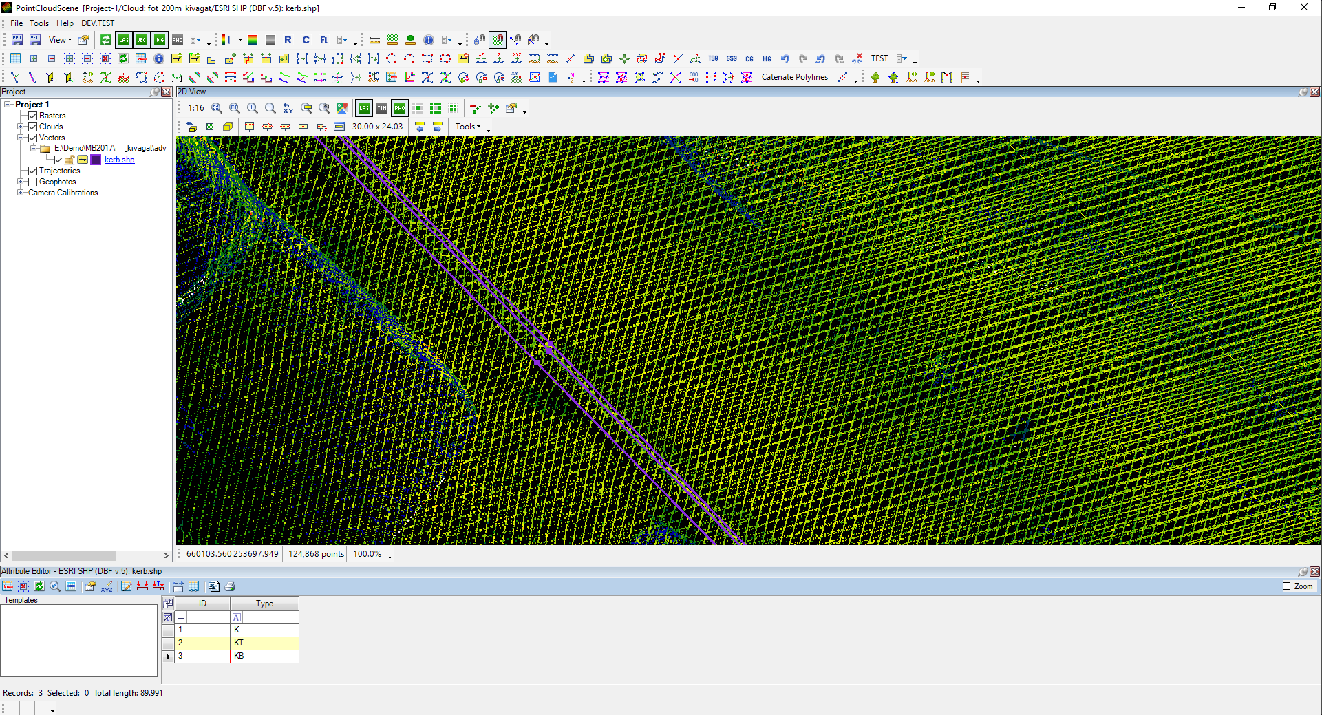
Start the New Element tool, and extract the kerb's top line in 3D view using point cloud snap. Click the points in the point cloud to have the polyline.
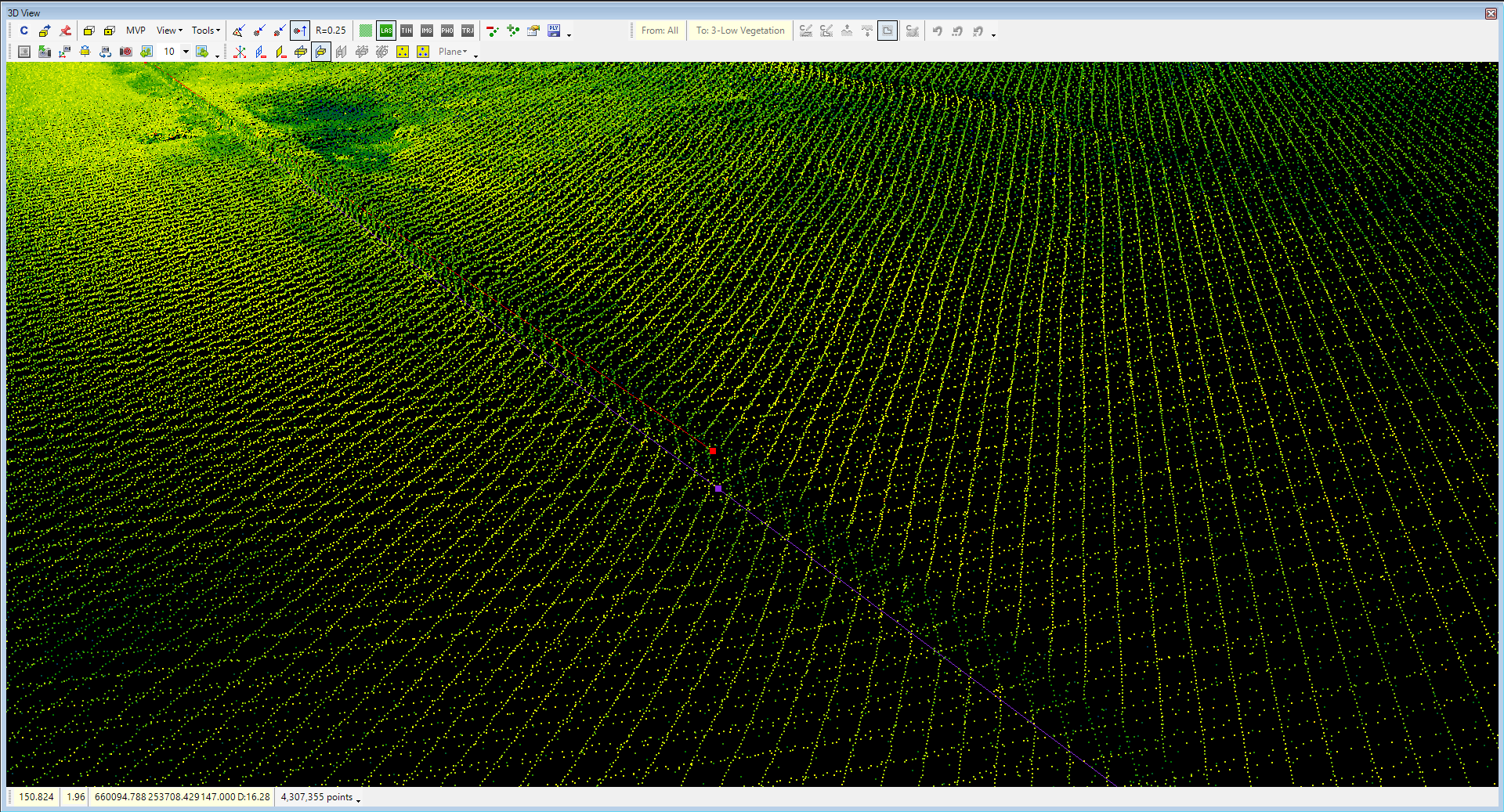
When all points are extracted, press enter to store the value and append the required attribute in the attribute table.
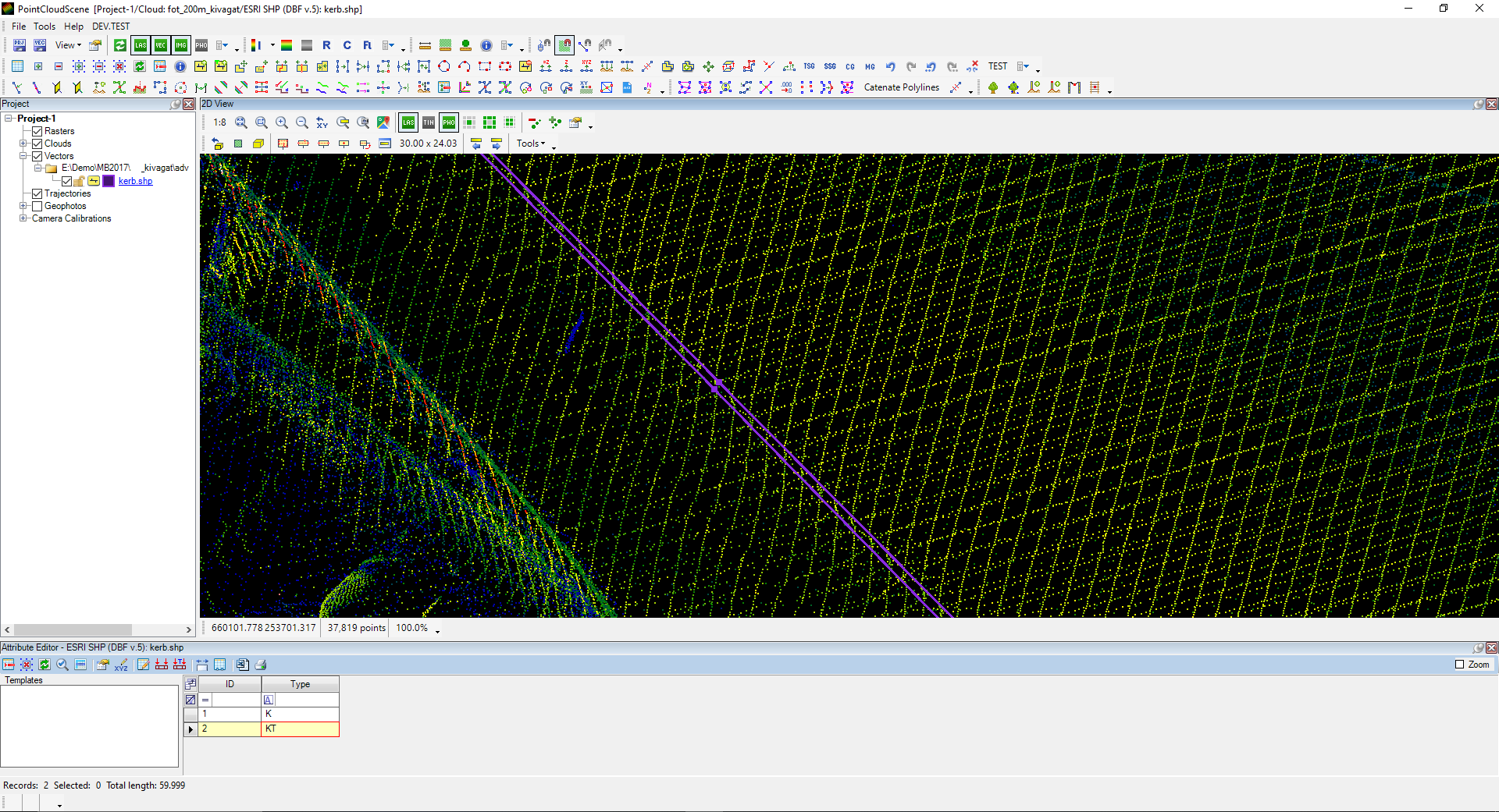
For the third line, the user can use the Parallel tool from the Shape Toolbar to speed up the process. After starting the parallel tool, select the line that needs to be paralleled (for practical reasons, the top of the kerb line), and click with point cloud snap to the correct location in 2D or 3D view. An indicator line will appear if the 2D view is used for parallel. After clicking the parallel location, the software will calculate the distance and elevation difference between the selected vertex and the clicked location (respectively, to the snap mode) and offer the parallel parameters to the user, which the user can adjust if needed.
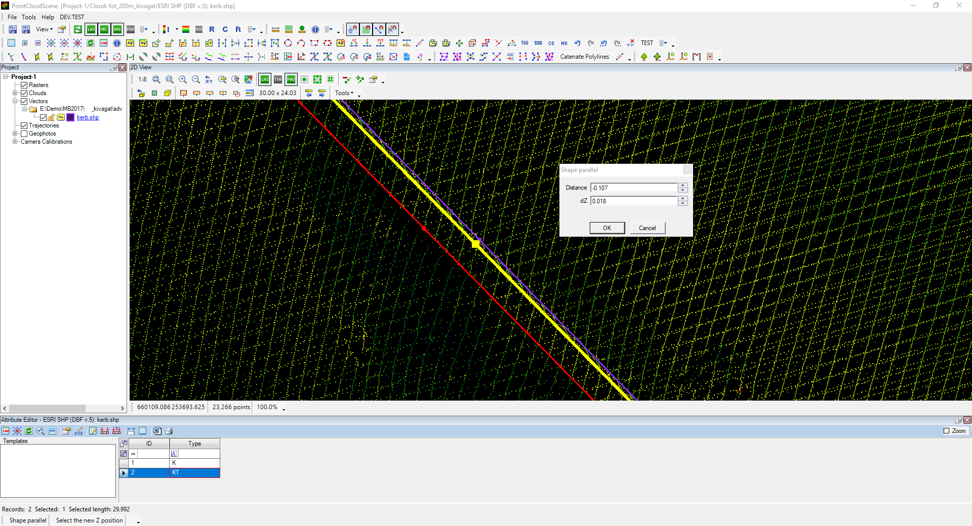
After creating the parallel line, always crosscheck the result in 3D to ensure the vertexes' elevation at the designated location. If the position of the line and vertexes is good, append the required attribute into the attribute table.
If the existing lines require fine-tuning, the following tools can be used from the Shape Toolbar. Keep in mind the snap mode setting upon modification.
- Move Shape Vertex - Move a vertex to a new location
- Remove Shape Vertex - Remove a vertex from a polyline/polygon
- Insert Shape Vertex - Insert a new vertex to the existing polyline/polygon
- Remove Item - Delete selected items
- Modify Vertex Z - Adjust one vertex's elevation visually on one of the views.
The method is more manual; let's discuss the second option on the other side of the road.
2. Approach - Extract the vectors and use templates for the attributes - As a record is being created, the template will auto-fill the attributes.
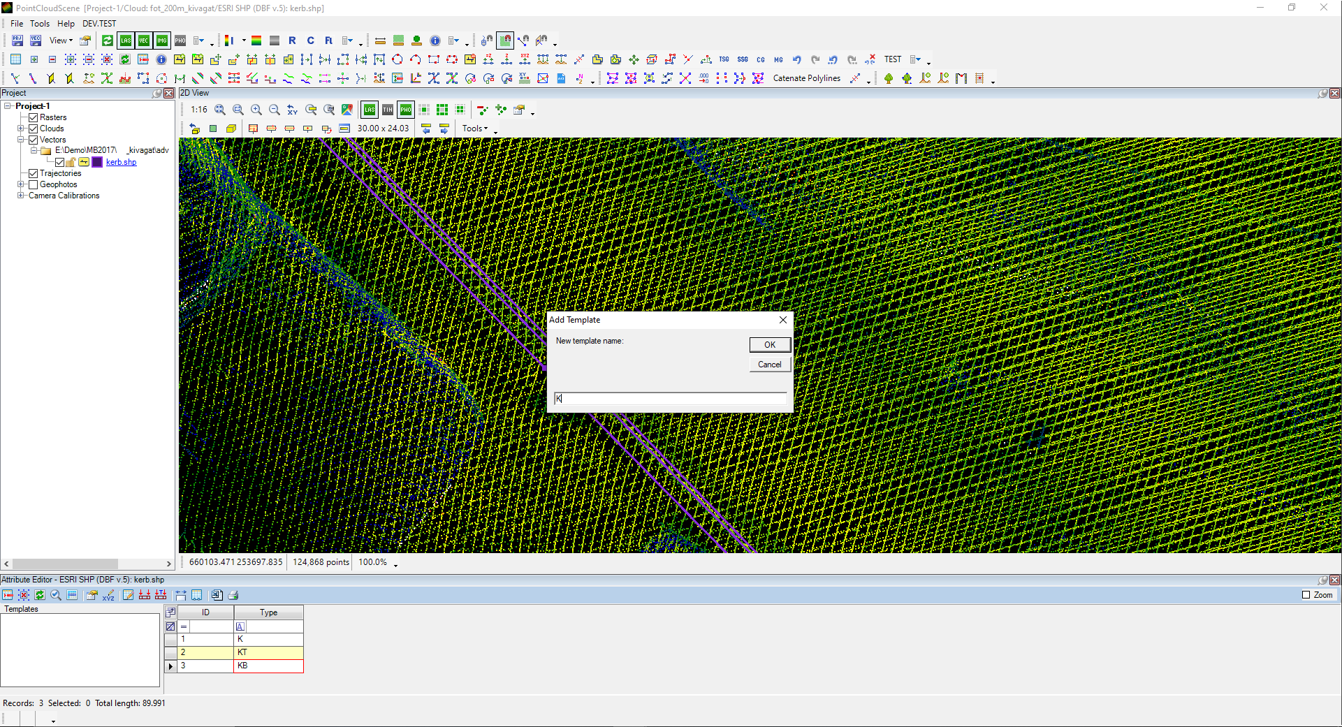
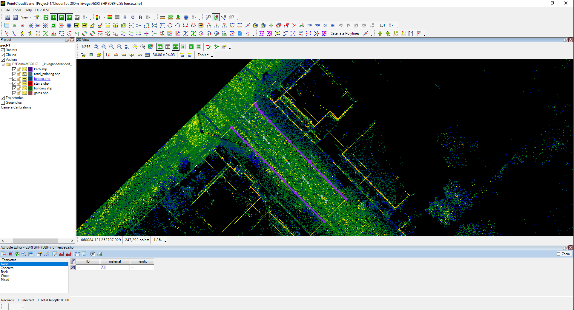
For this approach, the templates shall be created inside the attribute table. For this example, manual creation is being used. In our case, three templates are needed: K, KT and KB. To append these, right-click on the empty Templates area, select Add New Template, and enter the template name (which can be anything, but for simplification, the K, KT and KB will be used).

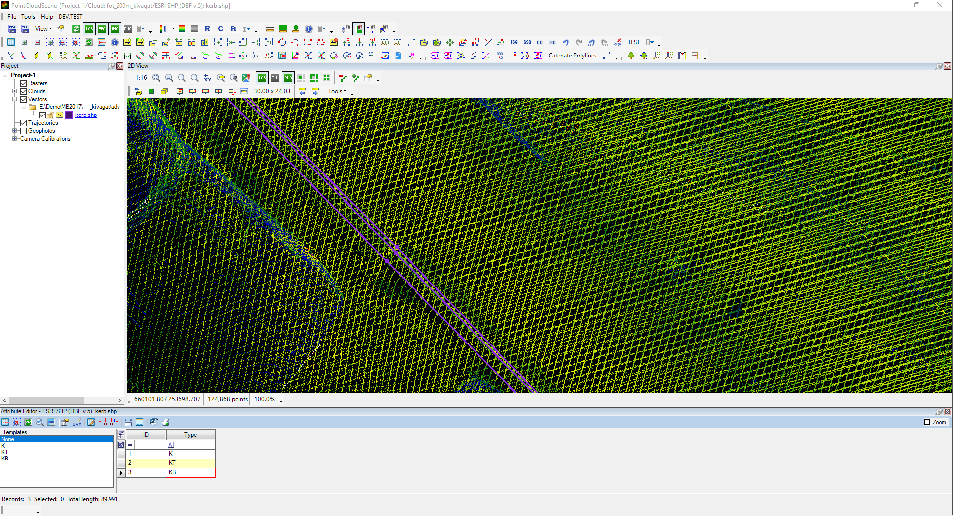
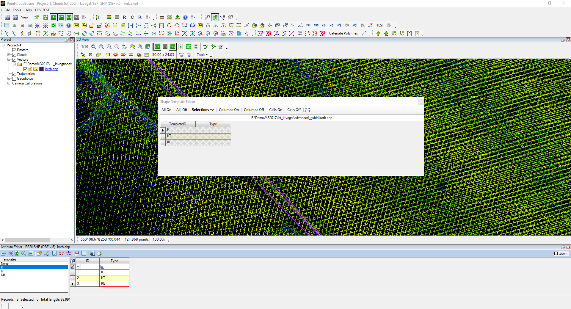
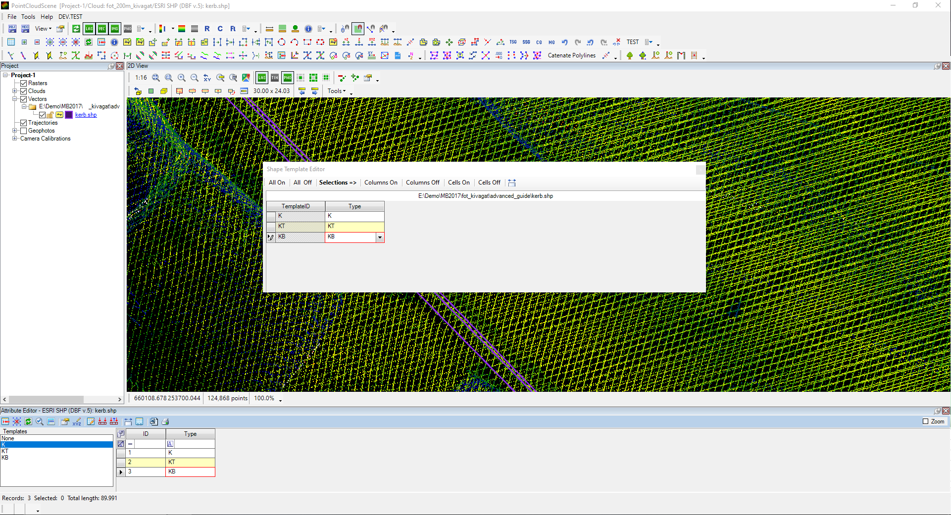
The creation and preparation of the templates have not yet been done. The templates can be selected, but the default values are not set; the attribute defaults must be prepared. Press right-click in the template area and select Edit Templates (a single edit is an option as well, but the multi-edit is better for our example, and a single template edit can be used only if a template is selected, and the right-click is happened on the exact template).


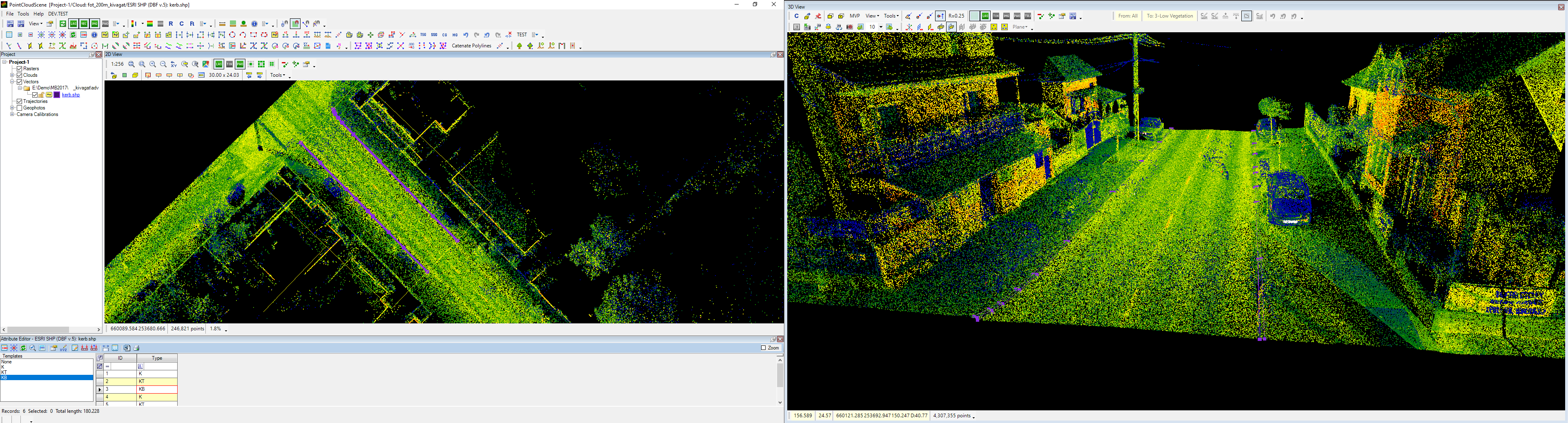
After the templates are set, the user can select an active template from the list - like layer select in CAD - and the new record will have the pre-set attributes when the drawing is performed. For our example, the other side of the road has been extracted using the templates. The K line has been extracted from 2D, and the KT and KB lines are paralleled.
If the wrong template is being used, select the record in the attribute table (or using the selection tools from the Shape Toolbar, and select the objects in the 2D or 3D view) and use the Apply Template to Selected Rows option from the attribute table toolbar. If a batch update is needed, but there is no suitable template, or only one or two attributes shall be updated, use the Apply Quick Template from the attribute table toolbar. If an object is done, the attribute table can be closed.
As the kerbs are ready, move on to the road paintings. A new polygon SHP will be created and saved for road paintings as road_paintings, which will not contain any attributes. Make sure that the new SHP is the active SHP. In our example, the road paintings are extracted as polygon, but if only the axis is required, the user can use a polyline SHP, and the extraction is the same as for the kerb lines; just a different object shall be extracted.
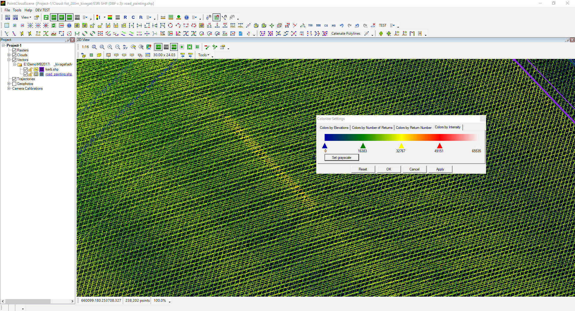
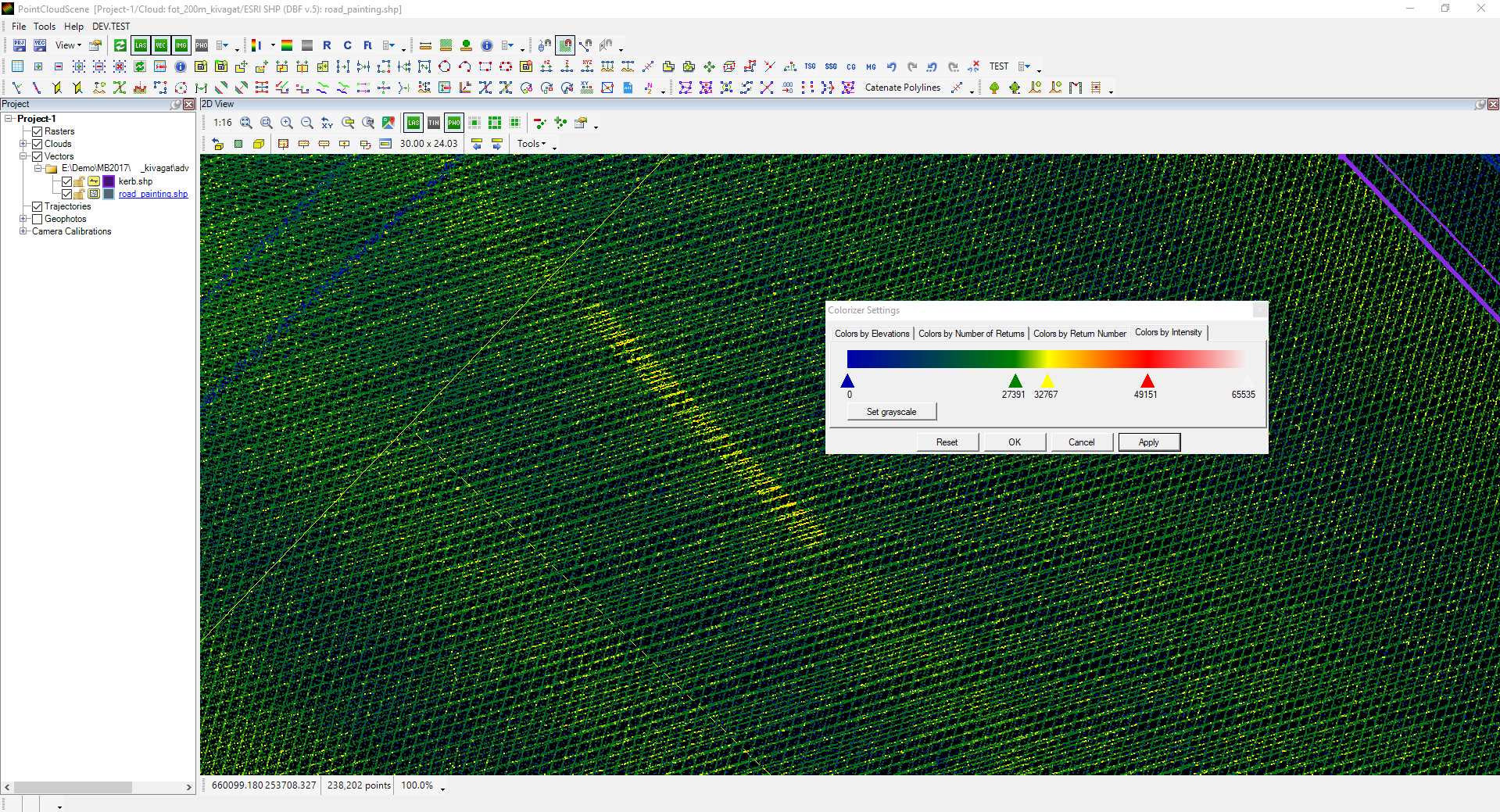
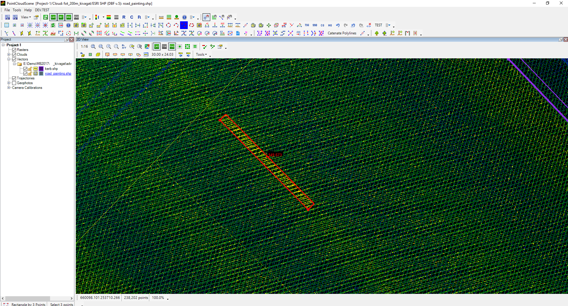
The rectangle tool is being used and using this tool in 2D view, as the user will see an indication of the resulting rectangle as a temporary line. If the road paintings are not exactly visible, tweak the intensity display using the Colorizer Settings from the Point Cloud Toolbar.
The rectangle tool is located on the Shape Toolbar. The user shall select 2 points and width for the rectangle. It is recommended always to pick the longer side of any rectangles first. The free point snap or point cloud snap can be used for this extraction, and the elevation shall also be adjusted.

The New Element tool can also be used to draw road paintings if the road painting is irregular or longitudinal. If road painting is not required as a polygon but a polyline, it is also an excellent approach to draw one side, parallel the polyline, close the ends and join the polylines to have a single element. Extracting and copying a single road painting for the other aspects is also possible. Keep in mind the snap modes during the extraction. In our example, all road paintings were extracted using the rectangle tool.
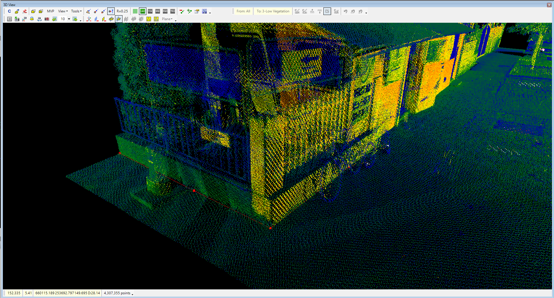
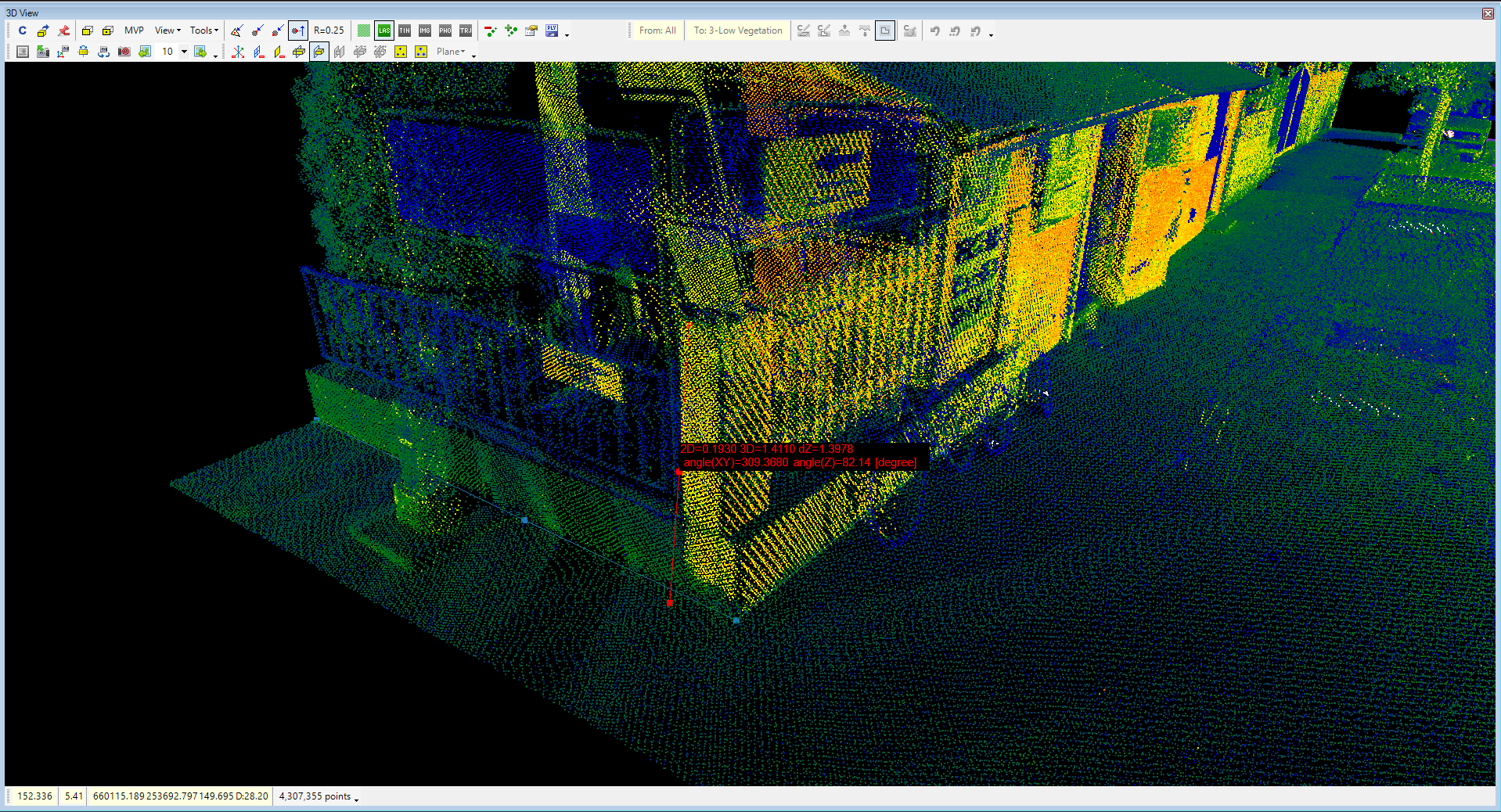
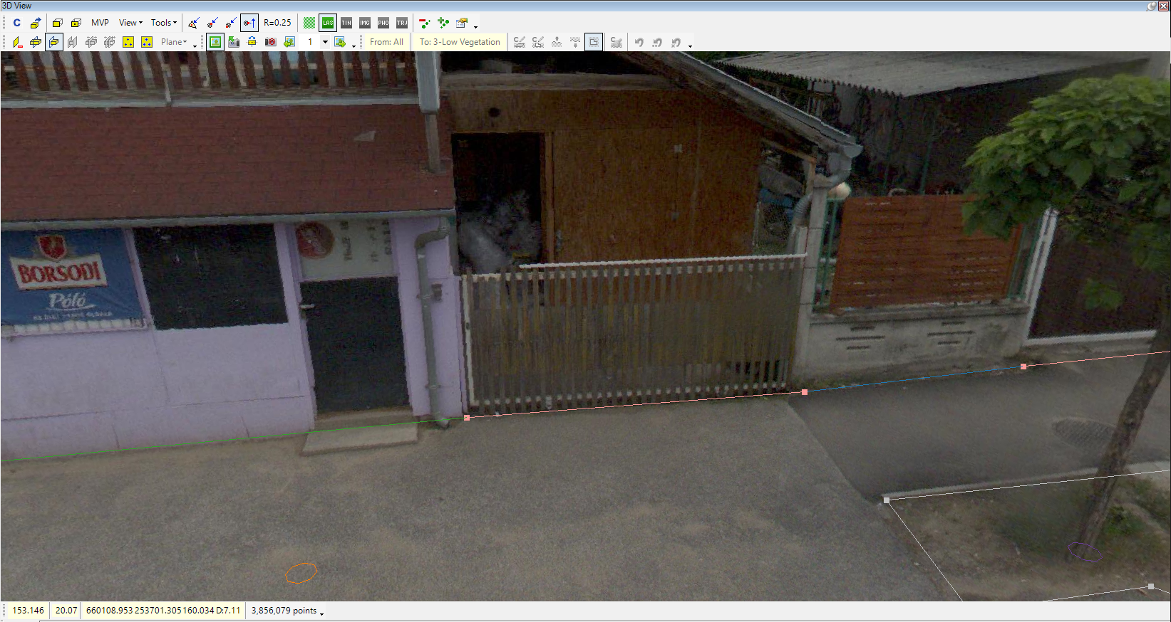
The following covered objects are fences. A new polyline SHP will be created for fences. In terms of attributes, the fence's material and height will be appended as attributes. The attribute assignment is described above. Templates will also be created fences, but the height of the fence will not be set, as this cannot be a fixed value; the user shall enter this attribute. The extraction can be performed in 2D or in 3D as well. As the edges of the target area are not covered only by fences, a building, a gate and stairs, polyline SHP will also be created, but these will contain no attributes. During the extraction, the active shape needs to be changed commonly.
The extraction has been carried out using the respective SHP files and templates for the fence. The Distance (2pt) tool from the Measure toolbar can measure the fence height. The measured value has been entered manually.
Sometimes, one or more vertexes cannot be placed in the required place while extracting the polyline or polygon object. This is not an issue. Feel free to misplace a vertex and correct it after the polyline/polygon has been stored using the modification tools from the Shape Toolbar. It is faster than starting the line again or stopping the extraction, as the required place is not visible.
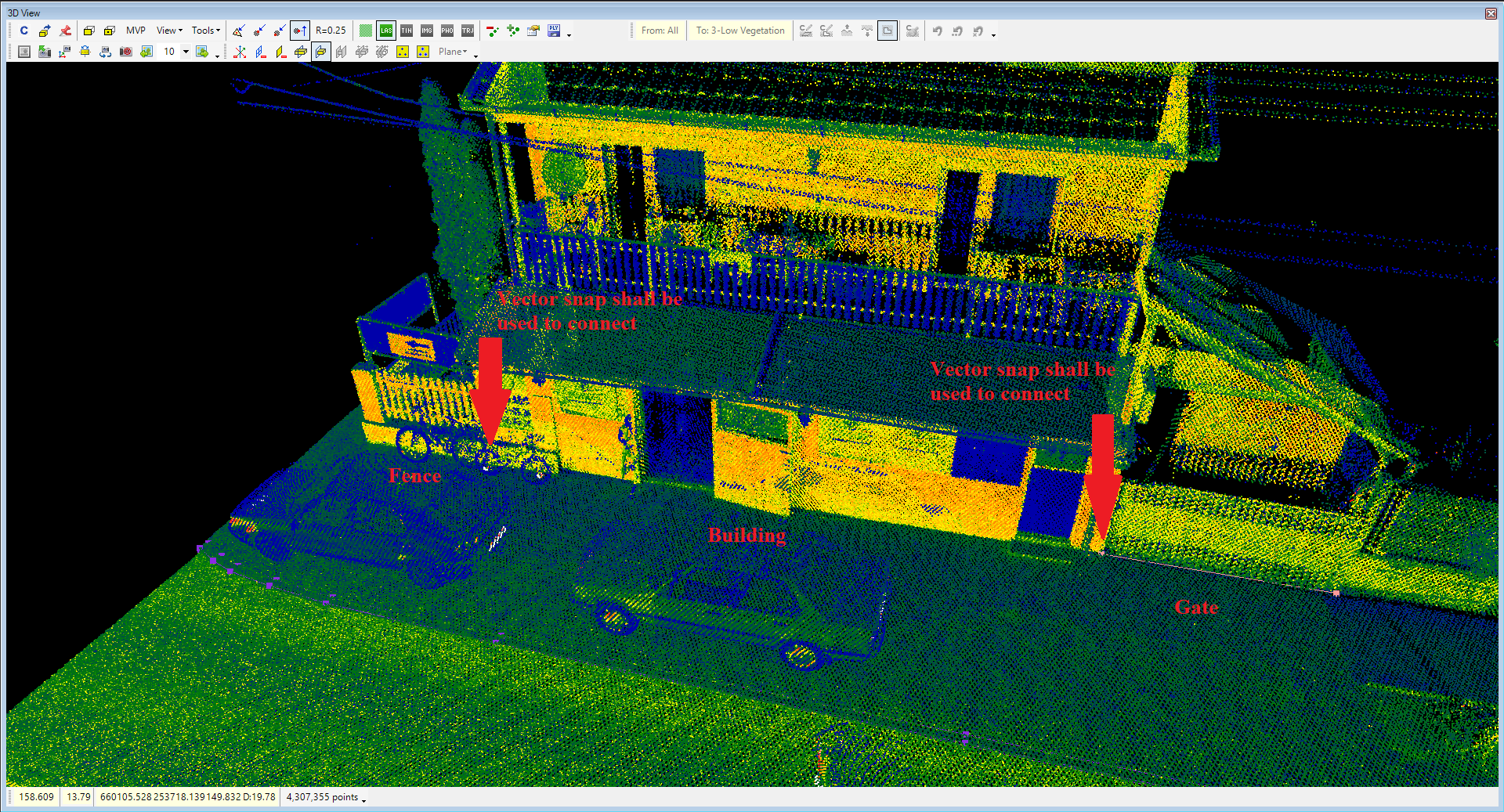
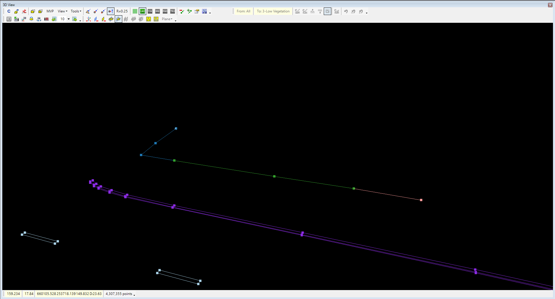
During the extraction of the fence object, the user might be able to join the polyline's start point to an existing vertex. For this, the first vertex of the new line shall be placed using the vector snap mode; then, the snap mode can be changed to point cloud snap to continue the extraction. In general, it is highly recommended to have vector snap as the ONLY turned-on snap mode when a connection is made to an existing line to avoid mis-snap by point clouds or free points.
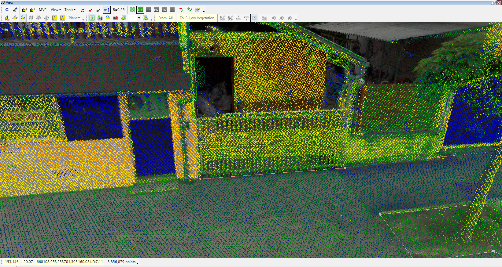
If the geophotos are available, the user can inspect the location using the Photos toolbar.
When fence-related objects are extracted, the areas between the road and the fence can also be extracted. To enhance the user experience in the 2D view, the user can label the fence lines in the 2D view by selecting the material field for Automatic Label from the vector properties.
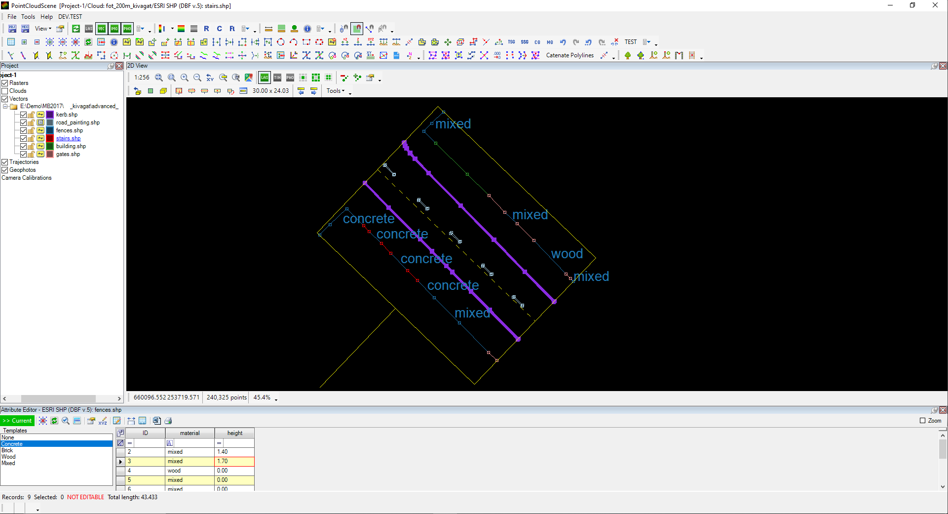
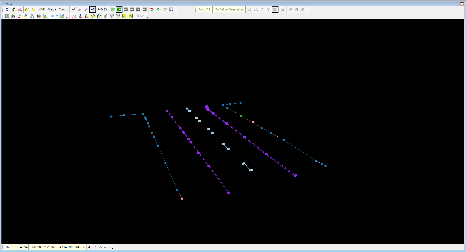
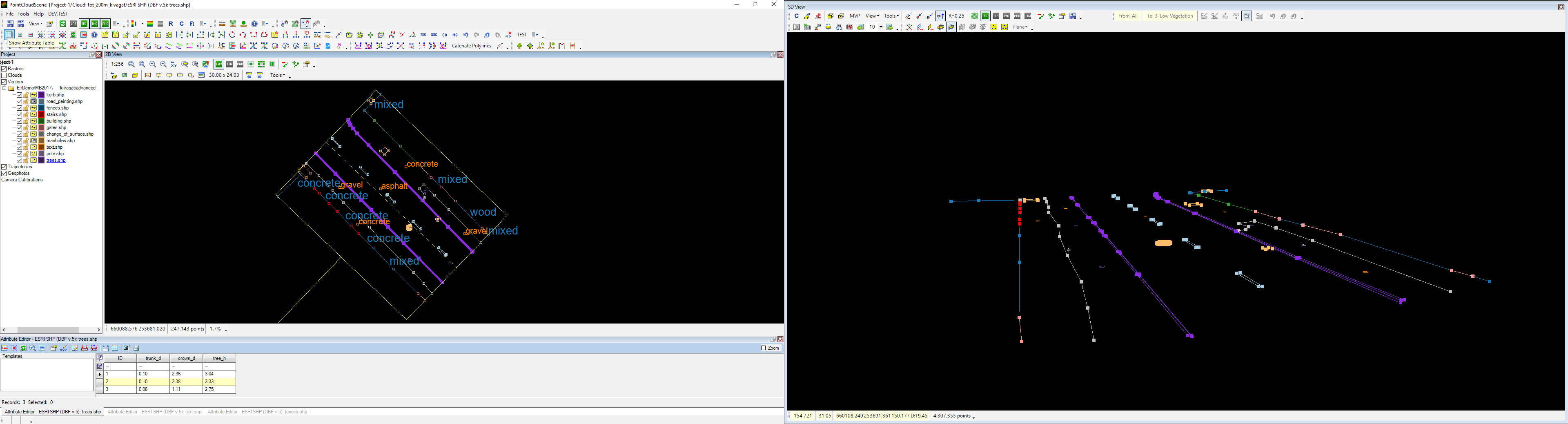
To fill the area between the kerbs and the fences, a new polyline SHP has been created to indicate the change of surface lines, and another polyline SHP represents the manholes. The previously described methods were used.
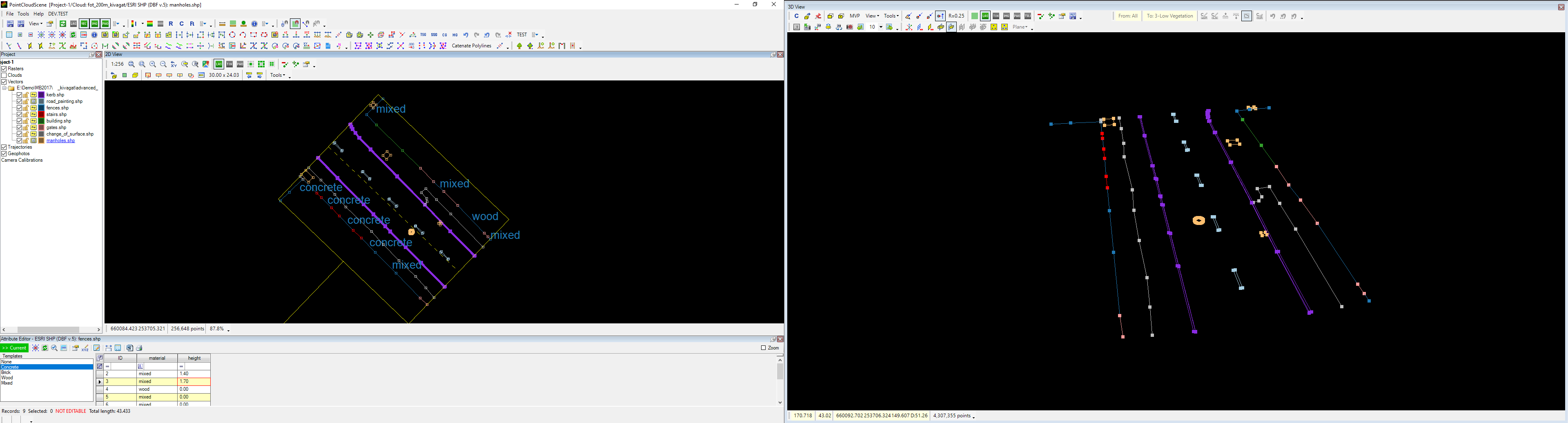
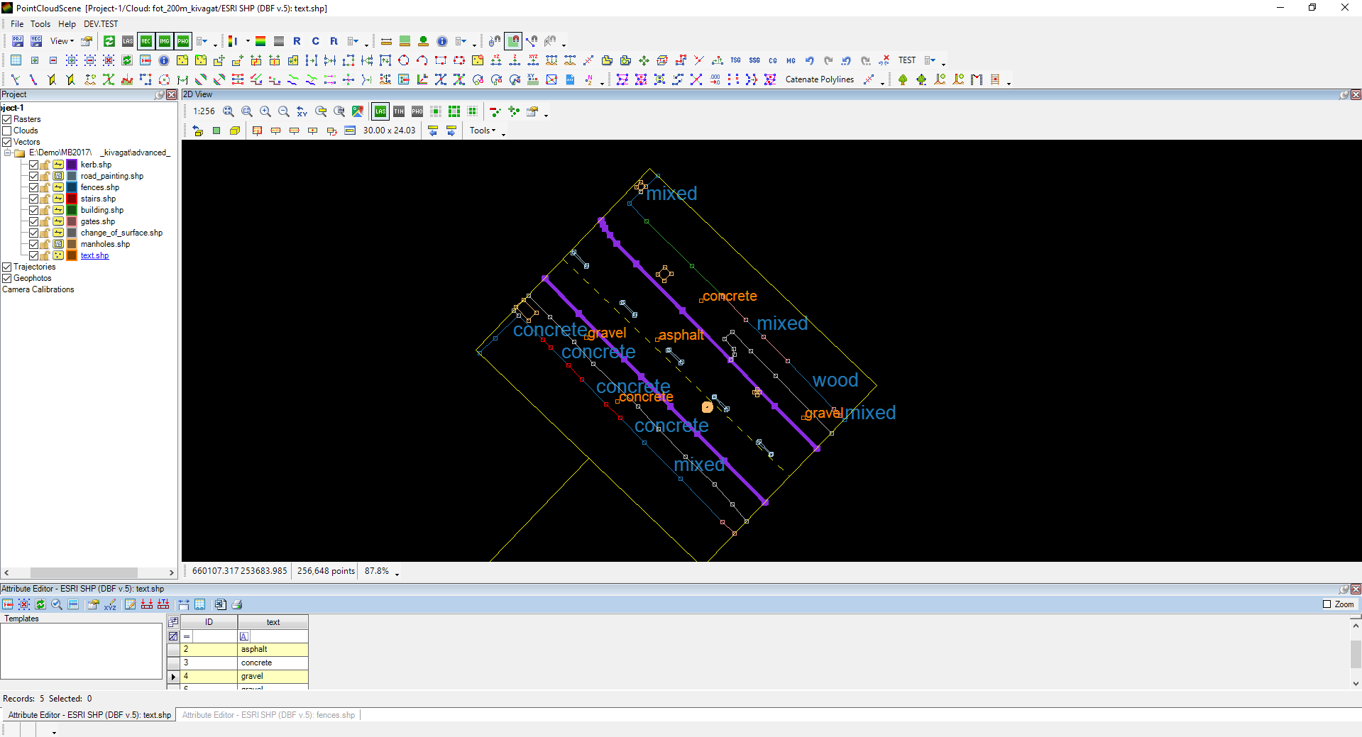
As the change of surface lines was extracted, it is required to indicate which area is what. For this, a point SHP with the name of 'text' has been created with the attribute of text. This will be used to identify the areas. To display this, the Automatic Label will be used for this point SHP. The New Element tool is used with point cloud snap to place the points.
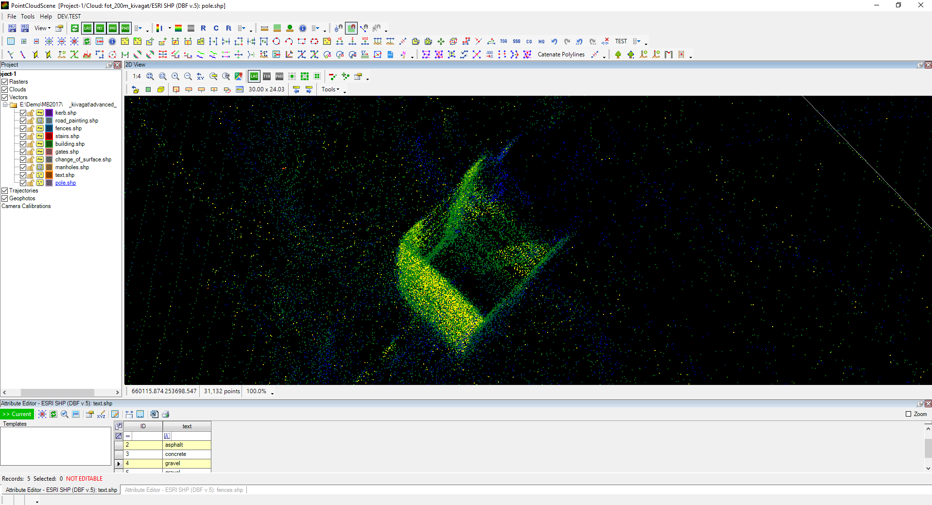
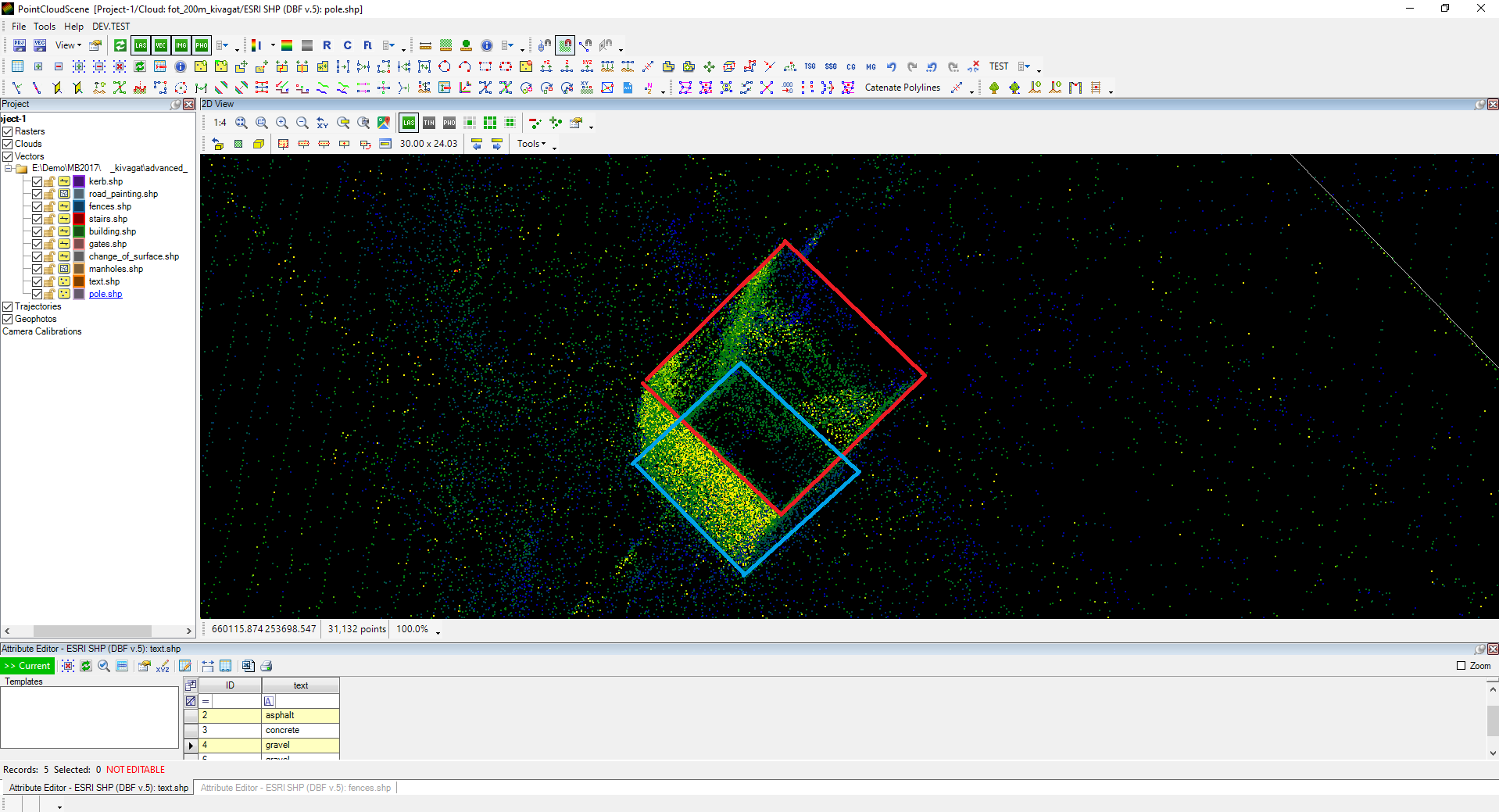
The next element to be extracted is the electric poles. For this extraction, a new point SHP has been created with the name of pole without attributes. The pole placement was performed in 2D using a free point snap, and the elevation was adjusted afterwards. Please note that if a pole-like object is being extracted, it might bend in some direction. If the vertex has been placed from 2D, always cross-check if the vertex has been placed in the correct location.
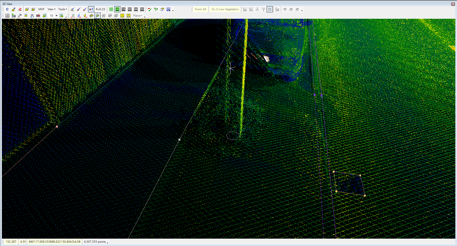
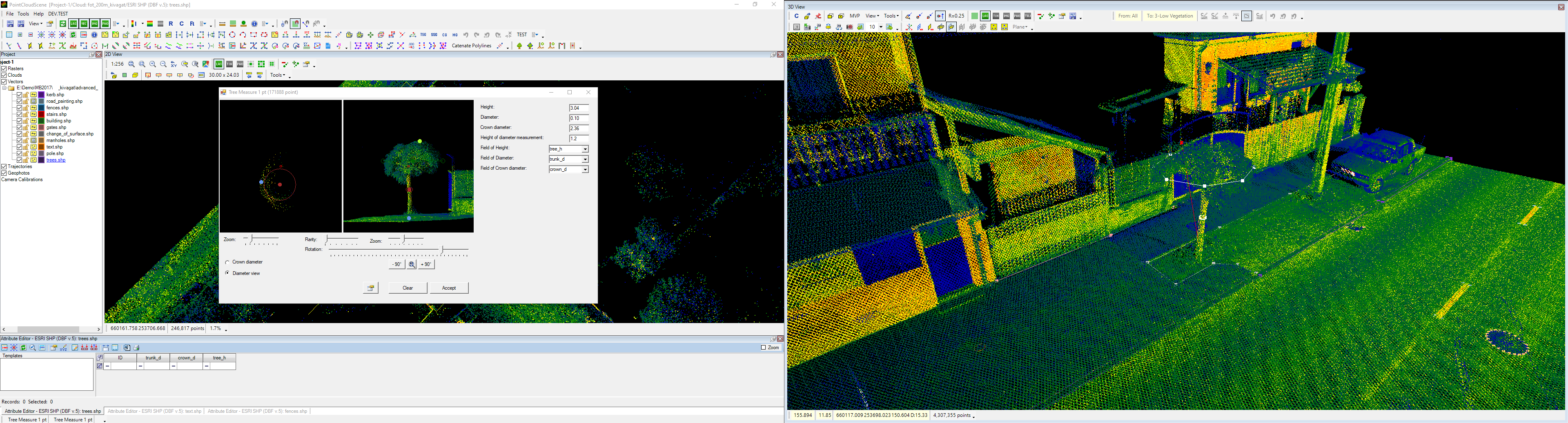
The last object to be extracted is the tree locations. For trees, a new point SHP has been created. To utilize a more advanced tool in PCS, this tree SHP will receive attributes for tree height (tree_h), crown diameter (crown_d) and trunk diameter (trunk_d) (the software can offer automatic tree attribute assignment, but this is not discussed here). The locations and the attributes are extracted using the Tree Measure (1pt) and (5pt) tools from the Complex Measures Toolbar.
The Tree Measure (1pt) tool has been used for the first tree. A single point on the tree has been selected, and the extractor will identify the tree and load the cloud to the views. The tree dimensions can be adjusted with the coloured dots, and the respective attribute fields shall be selected to store the attributes. After pressing Accept, the tree will be stored, the point will be placed, and the attributes will be assigned. If needed, the tree's location can be adjusted in both 2D and 3D views with the modification tools from the Shape Toolbar.
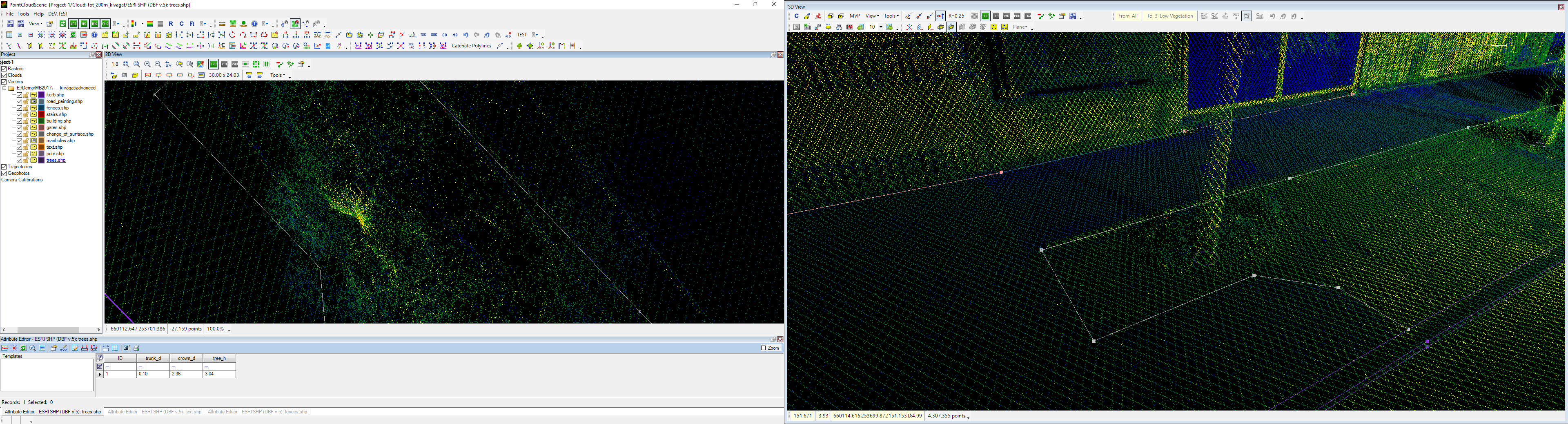
The Tree Measure (5pt) tool has been used for the other trees. The main difference is that using the 5-point extraction method, the user shall input all key points in the following order:
- Select a point on the ground
- Select a point on the tree trunk
- Select one edge of the crown
- Select the opposite edge of the crown
- Select a point on the top of the tree
After the points are selected, the extractor will load the tree, and the user can adjust the values. After pressing Accept, the tree will be stored.
With this step, the extraction has been finished for our current example; the finished drawing is now usable in other software like QGIS.
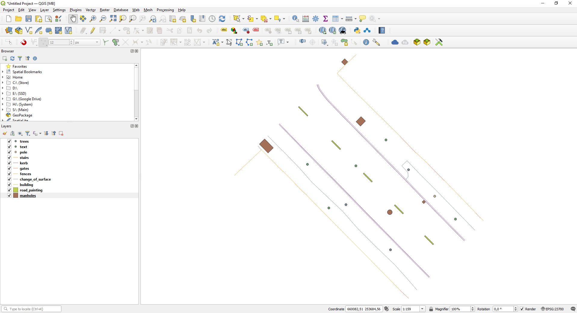
Based on the described methods, the users can extract vector information and attributes using PCS from the point cloud for general purposes.
For CAD-based extractions, please check this guide.
For surface and contour generation, please check this guide.
Please check this guide to check vector quality with the surface-cloud difference toolkit.