¶ Shape Toolbar 2
Shape Toolbar 2 was introduced with the Shape Layout Version 1 in the Q3-Q4 of 2023. The tools were available before under the Shape Toolbar - More dropdown menu, but in the new layout version, the tools received icons and were separated into new toolbars. The Shape Toolbar 2 is located in the Main Window. The tools are available if at least one SHP/FDB table is opened in the project. Otherwise, they greyed out.

The description of the tools is the following:
- Insert and Move vertex - This tool allows the users to select a polyline or polygon element and then add a vertex to the element. After starting the tool, the snap modes will be locked to free point and vector snap. The user shall select an element and then click somewhere where the new vertex will be placed. The vertex will be inserted between the two vertexes where the element has been chosen. The tool does not reset the current SHP selection.
- Insert vertex in multiple layers - This tool allows the users to insert a vertex to multiple polylines or polygons if they have the same geometry or they are close to each other within the set search interval. After starting the tool the following settings panel will appear:
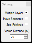
Selecting the Multiple Layers option will allow to insert the vertex to inactive SHPs as well. Selecting Move Segmenets option will move the freshly inserted vertexes to the location where the user clicked. Split polyline will split the polyline(s) or polygon(s) which are receiving the new vertex. The search radius allows the users to insert vertex to polylines which are close to each other, but do not have the same geometry.
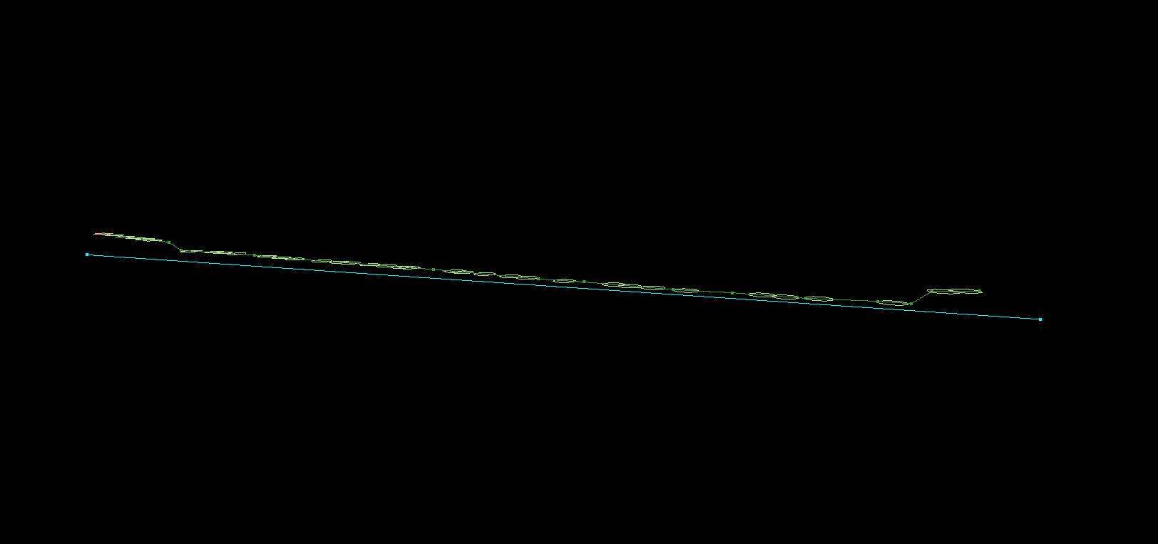
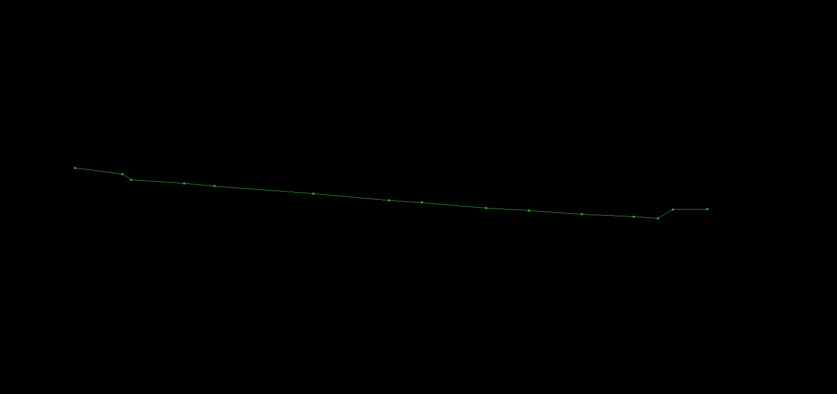
- Polycurve-Plane Intersection - This tool allows users to create a cross-section of the existing polylines and polygons using the auxiliary plane. Set an active polyline SHP where the cross-section will be stored. Place the auxiliary plane using the plane toolbar in 3D view. The tool will intersect all SHPs against the auxiliary plane and draw the cross-section through the intersection points. The intersection points will be inserted into the original geometries.
- Polycurve-Plane Intersection (multiple) - This tool is currently under development; the current version does not provide the designated result.
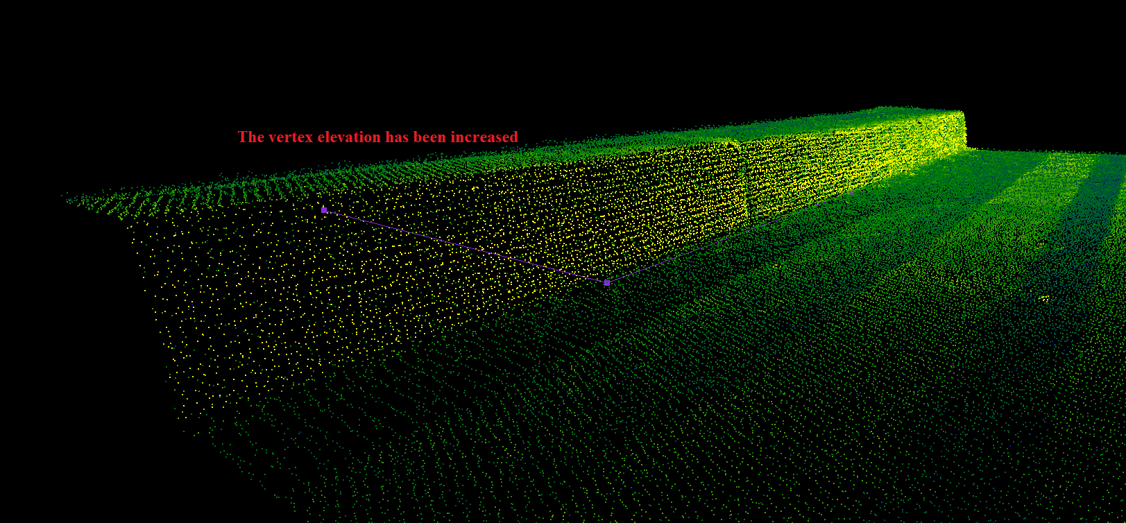
- New SHP object + Drape Lowest - This tool allows users to extract a new object (point, polyline or polygon) and instantly drape to the lowest point with the designated search radius. After starting the tool, the settings window will open.
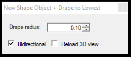
This tool has no option to modify the lowest setting to the highest or average as possible for the standard drape tool. The search radius can be adjusted, and the bidirectional option is available. If the bidirectional is selected, the drape can drape a vertex upwards; if unchecked, only downwards. If the reload 3D view is selected, the clip frame will be automatically resized and placed for the vertex location, and the 3D view will be reloaded. In that way, the user can instantly spot any issues with the drape.
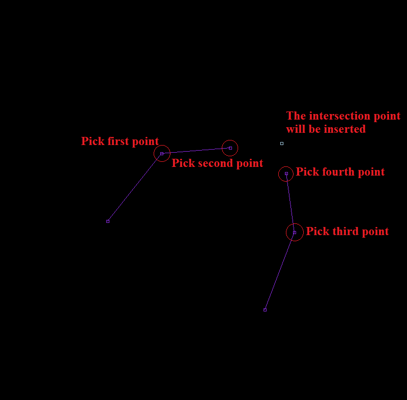
- Insert polyline intersections - The tool allows the users to perform an intersecting operation between 2 polylines (selected by clicking the elements or picking 4 points) and insert vertex to both polylines taking into account the elevation. After the tool has been started, the following settings panel will open:
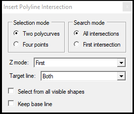
The user can adjust the input and output with the following settings:
Selection mode - Two polycurves - Select 2 intersecting polyline elements (non-active SHP elements can also be targeted, if “Select from all visible shapes” is checked), and the intersection will be performed. If there is no intersection, the tool will drop an error message.
Selection mode - Four points - Select 2 neighbouring vertex in the first polyline, then 2 neighbouring vertex from the second polyline, and the intersection will be performed. The tool will drop an error message if there is no intersection in the given segments.
Search mode - All intersections - If the selected polylines or segments have multiple intersections, all will be inserted.
Search mode - First intersection - If the selected polylines or segments have multiple intersections, only the first (considering the vector direction from the start point) will be inserted.
Z mode - Select, which Z value shall be assigned for the created vertexes. Using the Ignore option will interpolate the elevation at the source line, and the new vertex will not be moved in Z dimension.
Target line - Select, which selected line shall receive the intersection vertex.
Select from all visible shapes - This function allows the users to select polylines from non-active SHP files as well.
Keep base line - The first selected polyline is considered the baseline. If multiple intersections shall be appended, this checkbox shall be selected, and only the intersecting lines shall be selected, and the baseline remains selected.
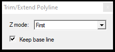
- Trim/extend - The tool allows the users to trim/extend polylines to a selected baseline inserting the common vertex points. After starting the tool, the settings window will open, where the user can select the Z mode, which elevation shall be used for the trim/extend function. Ignore option will keep the interpolated elevation for the source object. After starting the tool, the user shall pick two neighbouring vertexes from a polyline and select the polylines to be trimmed/extended to the selected baseline. Using the “Keep base line” option will enable trimming/extending multiple lines against the selected polyline segment. The tool can target any SHP, including non-active SHP files as well. After the trim/extend has been performed, both lines will receive a common vertex at the intersection point, and the elevation will be set as the user selected in the Z mode dropdown.
- Generate Cross-Sections - This function allows the users to create cross-sections from the point cloud based on the pre-selected locations. The tool can provide the proper output only if the active SHP is a polyline SHP, and it contains all cross-section locations, and each location is a polyline with exactly two vertexes. The tool will inspect the cloud based on the parameters and generate the cross-sections and support files. The tool will generate cross-sections for all locations inside the active SHP file. Please note that the SHP files will be generated first, but as long as the software does not prompt the user, it's done; it's running in the background. Wait for the Done window before doing anything else in the project.
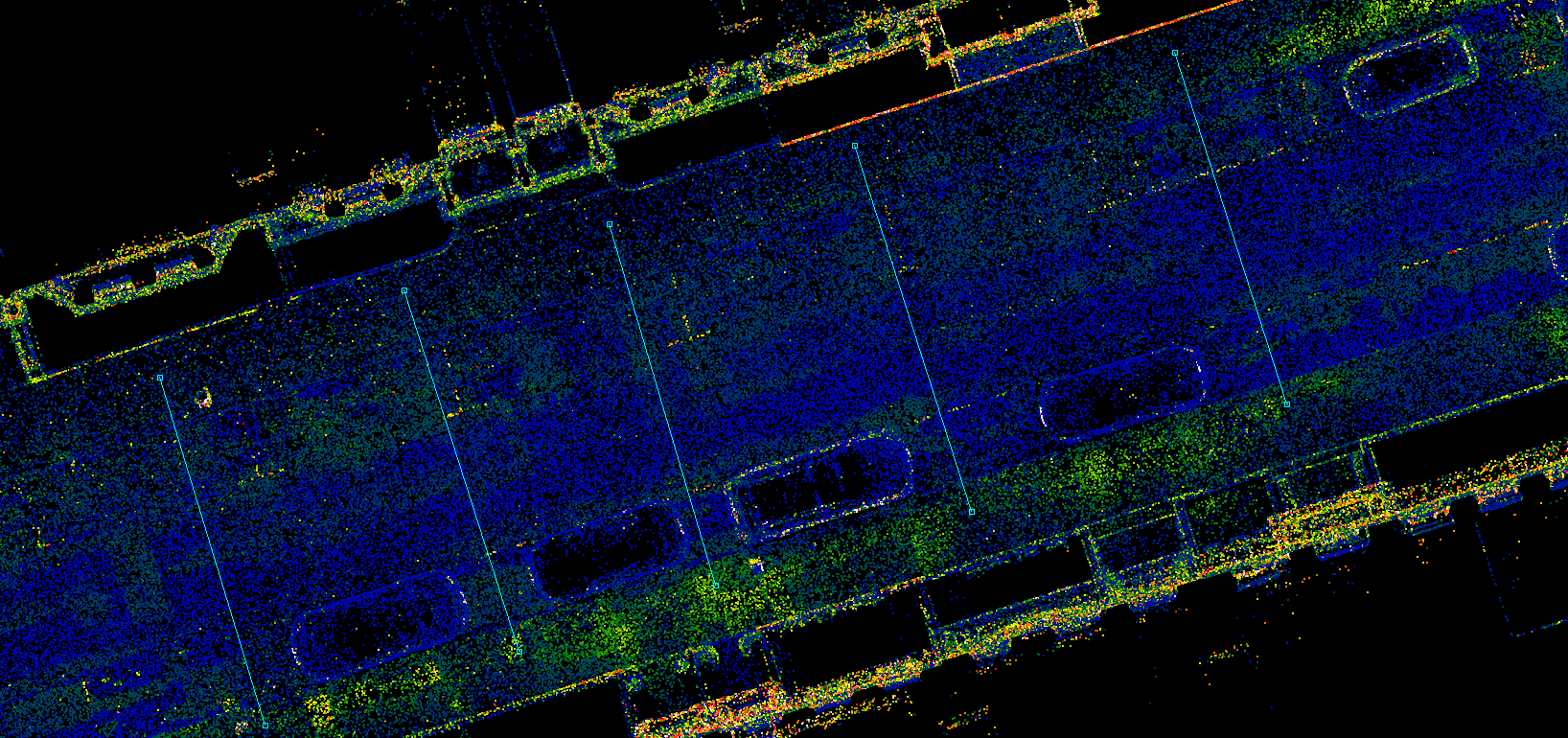
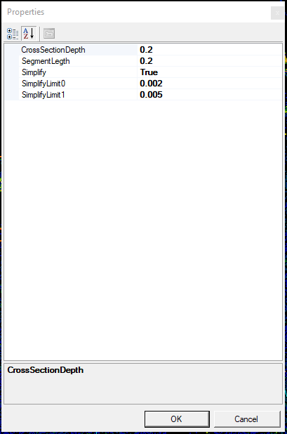
The user can specify the cross-section's maximum depth and segment length in the settings dialogue. The software first tries to identify the key points and then simplifies the received points by the given limits if the simplify is set to true. Upon running the tool, the software will generate multiple SHP files containing the output points and section polyline.
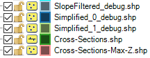
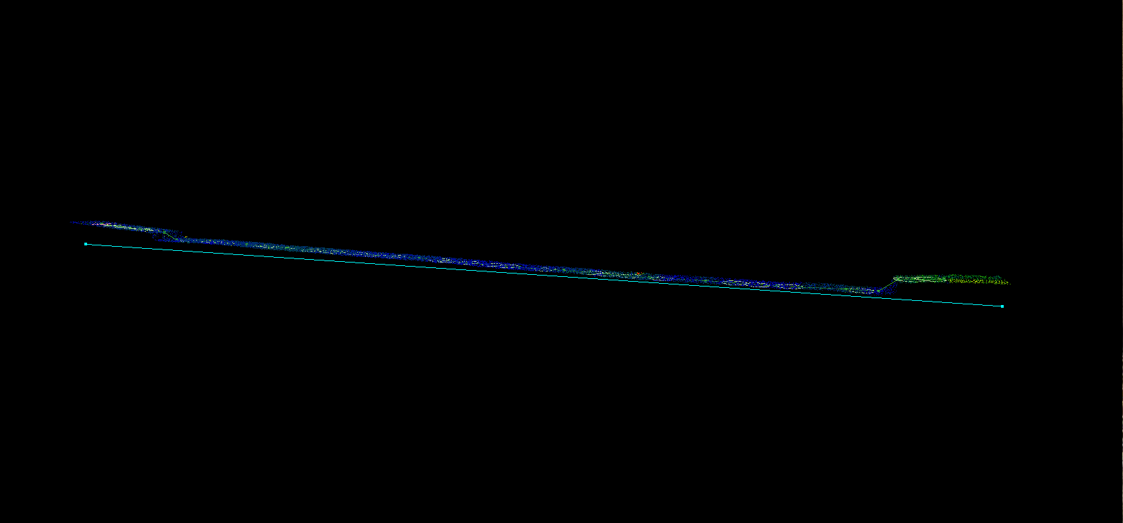
The generated SHP files contain points; one SHP contains the cross-section itself.
- Insert Corner Point - This function can be used only with an active point SHP. After starting the tool, the snap modes will be locked to free point and vector snap. The user can pick 2-2 points. Using the 2-2 points, the user can measure/indicate two lines, and the software will insert the intersection point of the two lines. The elevation will be interpolated from the input line directions. The tool does not reset the current SHP selection.
- Insert Circle Center Point - The function can be started only with an active point SHP. The tool asks the user to select 3 points, and based on the 3 points, the tool will insert a centre point for the circle defined by the 3 points. After starting the tool, the snap modes will be locked to free point and vector snap. The tool does not reset the current SHP selection.
- Catenary - This tool allows the users to extract cables with a given section length based on 3-4 selected points. The tool does not inspect the cloud and only creates a spline based on the selected points. The tool is designed to extract a spline between 2 poles with a single radius. After starting the tool, the software will ask for the segment length; the line will be divided based on this length. After starting the tool, the snap modes will be locked to point cloud snap.
- Copy Multiple Shape Item - The function allows the users to copy the active selection with a basepoint to a new location in 2D/3D view. The tool enables the users to use all snap modes. The tool requires an active selection for the active SHP (for at least one item). The function can accept any type (point, polyline, polygon) SHP as active. After starting the tool, the software will prompt the user to decide whether or not the attributes should be copied. If yes, the attributes will be the same as the source object; if not, the active template - if applicable - will be applied. There is no need to select objects; the active selection will be automatically used. The first point that the user shall choose will be the base point for the copy, and after that, the user can copy the selected elements multiple times until right-click or ESC has not been pressed. If the copy is in progress, the right-click allows the user to pick a new basepoint; if the tool is started but no basepoint is selected, the right-click will terminate the tool.
- Move Multiple Shape Item - The function works like the above-described Copy Multiple Shape Item tool but only moves, not copies, the active selection.
- Construct Parallel Lines - This tool allows users to construct parallel lines at set distances. The tool enables the users to use all snap modes. After starting the tool, the software prompts the setting window, where the dimensions (according to the vector direction) can be set. After that, the user can draw parallel lines with the set distance. The centre line will not be extracted; only the parallel ones will be extracted.
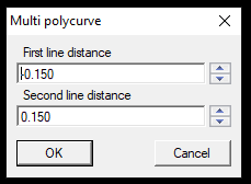
Please note that the numbers, by default, place the parallel lines left and right, as the first line has a negative sign. If both numbers are negative or positive, the lines will be constructed on one side, enabling the user to draw single-sided lines if an object requires it (for example, a rail or drainage). The elevation will be the same for both lines.
- Extract Multiple Lines - Standard and Tracking - This tool allows the users to extract multiple lines with a single command using separate SHP templates. The tool enables the user to extract up to 100 lines simultaneously using a cross-section view, where the user can adjust the location of the vertexes using dots. This tool can be handy for linear extractions such as highway and train lines. It is highly recommended that a window arrangement where the user can use the 2D view and the extraction window together, as both are required.
After starting the tool, the software will prompt the user if the tracking mode shall be used. If yes is selected, the axis can be a single line, and this single line becomes the target of the tracking. If no, the user shall pick two points that will specify the extraction's direction. All snap modes are available to select these two points (only vector snap for tracking mode). Select the first and second points in the 2D view. The direction will be marked with an arrow; the first point location will be the first cross-section location.
After the direction has been set, the settings window will appear, where the user can set the dimensions of the cross-section clip frame and the number of lines. The section will be a clip frame with the given settings using profile mode (all points are forced into the plane of the clip frame axis).
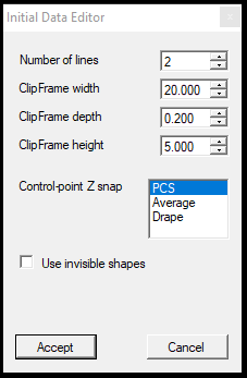
The settings are the following:
Number of lines - This setting adjusts how many lines shall be extracted with the tool. Separate SHP files and separate templates can be used for each.
ClipFrame width - The width of the cross-section. For example, if the user has a road with two lanes, setting it above 10 meters is recommended so the cross-section will cover the whole road.
ClipFrame depth - The depth of the section. The tool will force all points to a single plane - just like using profile mode at the Clip frame toolbar - from the whole depth of the section.
ClipFrame height - The tool can limit the vertically visualised amount of points in the extraction window using this setting. If the user extracts, for example, kerbs, 1 meter is good. If the user extracts higher slopes at the edge of a highway, setting it higher than the slope itself is recommended.
Control-point Z snap - To move the clip frame to the following location, the user shall click in 2D view. This click defines where the cross-section clip frame will be placed. The snap of this click can be a standard PCS snap (related to the active snap modes), can result in an average elevation value from the cross-section clip frame content, and can be draped to the ground level with the last used drape settings. The default setting is suitable for most of the use cases.
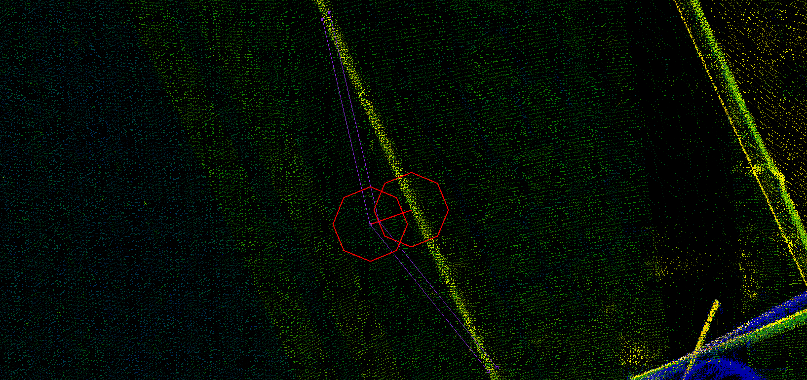
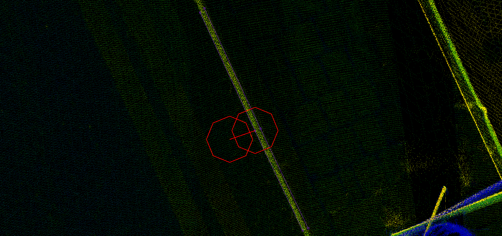
Use invisible shapes - As the lines are extracted with multiple sections, they are drawn in the 2D view as white lines indicating the process. If this option is selected, these indicator lines will not be present in the 2D view.
After pressing accept, the SHP/Template layout selector will be prompted.
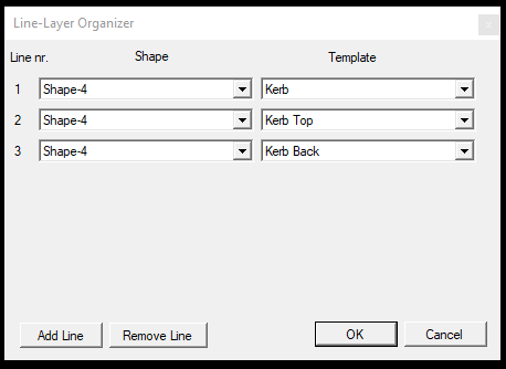
In this layout manager, the user can select which shape and template shall be used for which line marker. These SHPs and templates will be used to create the lines. If needed, the Add/Remove Line option can be used to add another/remove the last line. Removing a line is not possible in the current version of the software. The SHP selector allows the selection of polyline SHP files, and the templates can display existing templates. Pressing OK will start the extractor tool.
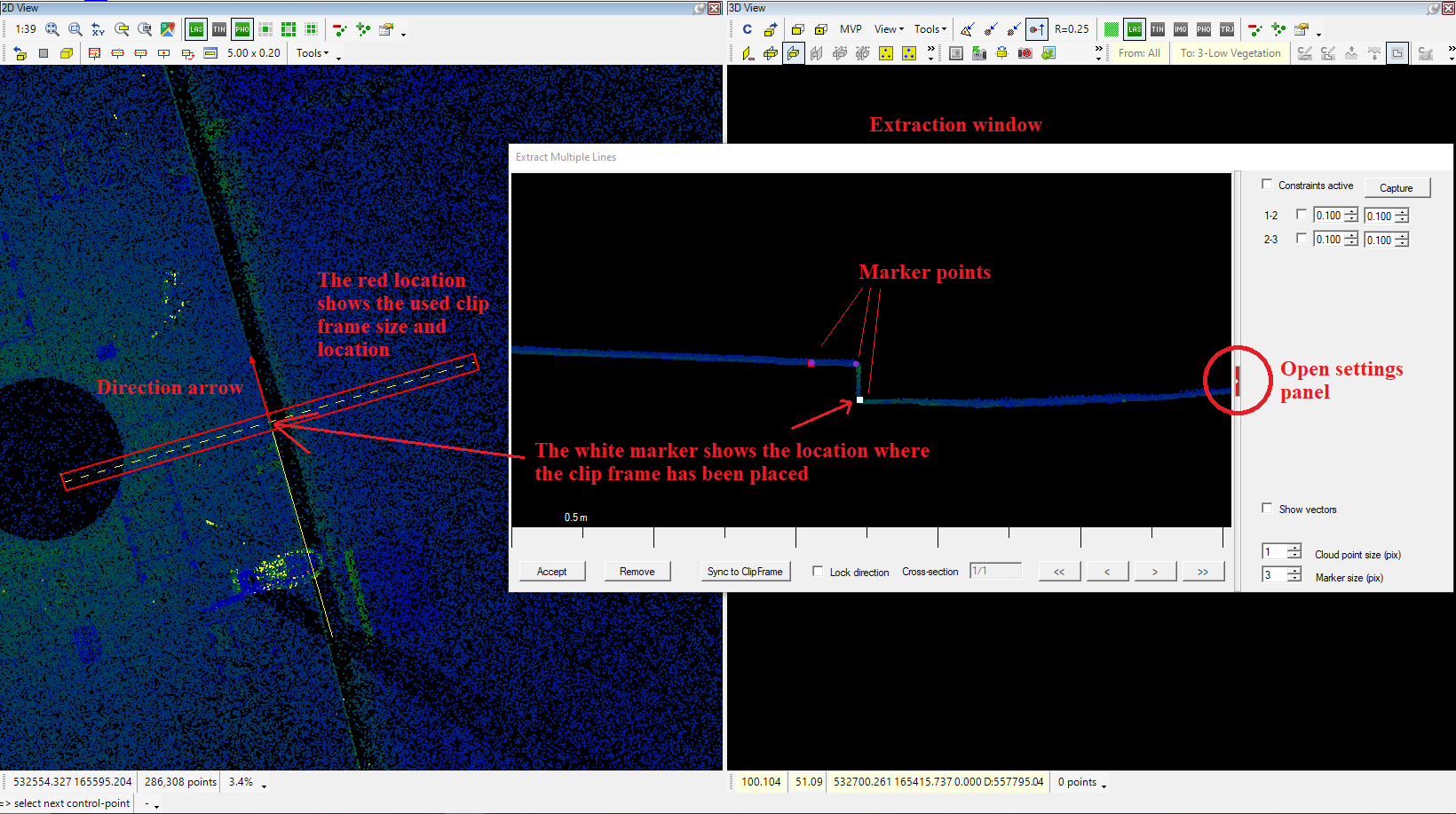
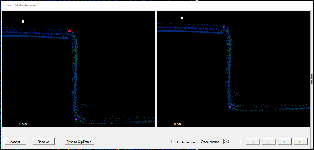
After starting the extractor, the first clip frame will be placed in the 2D view, and the extractor window will show the marker points. There will be as many markers as defined lines. If the user hovers the mouse over a coloured dot, a pop-up text will display the dot's SHP and template name to help the user. The white dot is where the clip frame has been clicked; it cannot be moved and might overlap with the line markers. The dot colour is aligned with the SHP colour. The user can pan and zoom in the window using the mouse. The tiny red icon opens the settings panel on the right side, which is closed by default. If the dots are aligned, to select the following cross-section location, click with the respective snap mode in the 2D view, and the software will load the next section, and the 2D view will display the temporary lines with white. The 2D view refreshes as the dot positions are changed.
The extraction window tool functions are the following:
At the bottom of the extraction window:
Accept - Accept the extraction. This button shall be pushed last, closing the extractor and saving the linework.
Remove - Remove the current cross-section location from the cross-sections. The next and previous sections will be intact.
Sync to ClipFrame - Holding down the CTRL button will allow the user to resize the clip frame on the 2D view as described in the clip frame article. If the user resizes the clip frame, the sync will not be automatic; the user shall press this button to sync the extractor view. The next selected cross-section location will use the last clip-frame size.
Lock direction - By default, the clip frame direction is calculated from the first and second (or subsequent) point location, and the direction will be aligned to this angle. If this checkbox is selected, this calculation is ignored, and the same direction will be kept for the clip frame.
Cross-Section counter - The software will show the total sections and the active number. This number might change as the user can move between the sections (so the user can go back to previous sections as well).
First - Previous - Next - Last cross-section arrows - These arrows help the user to navigate between the sections. If the user navigates to a section, the dots can also be modified later. If the user navigates to an existing record, it can be removed with the remove function. It is impossible to append a new section between the records; the new section will always be appended as the "last section". The 2D view will display the active section as the clip frame will be placed upon the location.
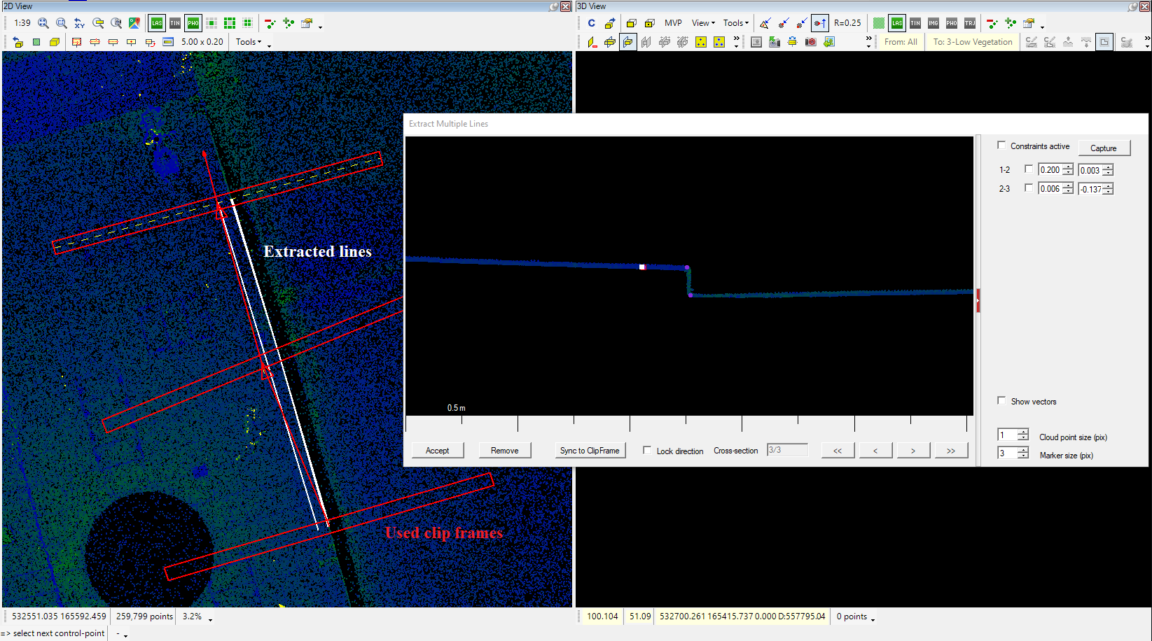
At the settings panel:
Constraints panel - In this panel, it is possible to "lock" the dots together. It will always present the N-1 option, where N is the number of lines in the extraction. The capture button allows the users to capture the distance between the dots, and the lines can be locked against each other using the checkboxes. If required, the distances can be adjusted manually. A dot can be locked only to the previous dot, which can be chained. In the extraction window, only the smallest number of dots can be moved if the dots are chained. If 1-2-3 dots are chained, the 1st dot can be moved; the other two will not move upon dragging. This function can be handy if some lines are extracted with a fixed arrangement, like kerbs.
Show vectors - Show existing vectors in the extraction window.
Cloud point size (px) - Adjust the point cloud point size in the extraction window.
Marker size (px) - The dot marker size in pixels in the extraction window.
If the right-click is pressed in the extraction area, the right-click menu will appear:
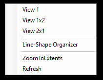
Users can arrange new views in the right-click menu to see different cloud parts.
Selecting the line-shape organizer will enable the user to add new lines to the current extraction. If a line is added after multiple existing sections, the new line shall also be set on the previous sections. The Zoom to Extent will zoom to the extent of the section, and the refresh will refresh the view if needed manually.
If the extraction has been finished, the Accept button can be pressed, and the lines will be created in the respective SHPs. The tool will ask the user to close the polylines. If yes, the software will connect each line's start and end points. The user can close the tool by right-clicking outside of the extraction window. The tool will prompt the user the window will be closed, and the extraction will be lost.
- Copy shape items from the current shape into another shape - This tool allows the user to copy the currently active SHP selection elements to another SHP of the same type. The software will prompt the user if the attributes are copied. If yes, and the target shape has the respective attributes, the attributes will be copied; if not, the currently active template in the target SHP will be applied. It is the same as Copy Geometry in the Shape toolbar, but not for a single element but for the whole selection.
- Move shape items from the current shape into another shape - Same as Copy shape items from the current shape into another shape, but instead of leaving a copy inside the source SHP, it will move the selected elements to the target SHP of the same type.
- Move Vertex by offset - This tool allows the users to define a distance and direction in one of the views, and the selected vertexes will be offset with this distance and direction. Starting the tool will set the snap mode to free-point snap, but the tool allows all snap modes during the selection of the offset direction and distance. The user shall select the first and second points. The distance and direction will be used for the offset. Consider the snap modes when determining the distance. If only the XY offset is required, use free-point snap to define the offset; if the XYZ shift is needed, use point cloud snap. After the offset is defined, the snap mode will be locked to vector snap, and the user can select vertexes from the active SHP only. The tool works with all types of SHP files (point, polyline, polygon). Starting the tool will reset the current SHP selection.
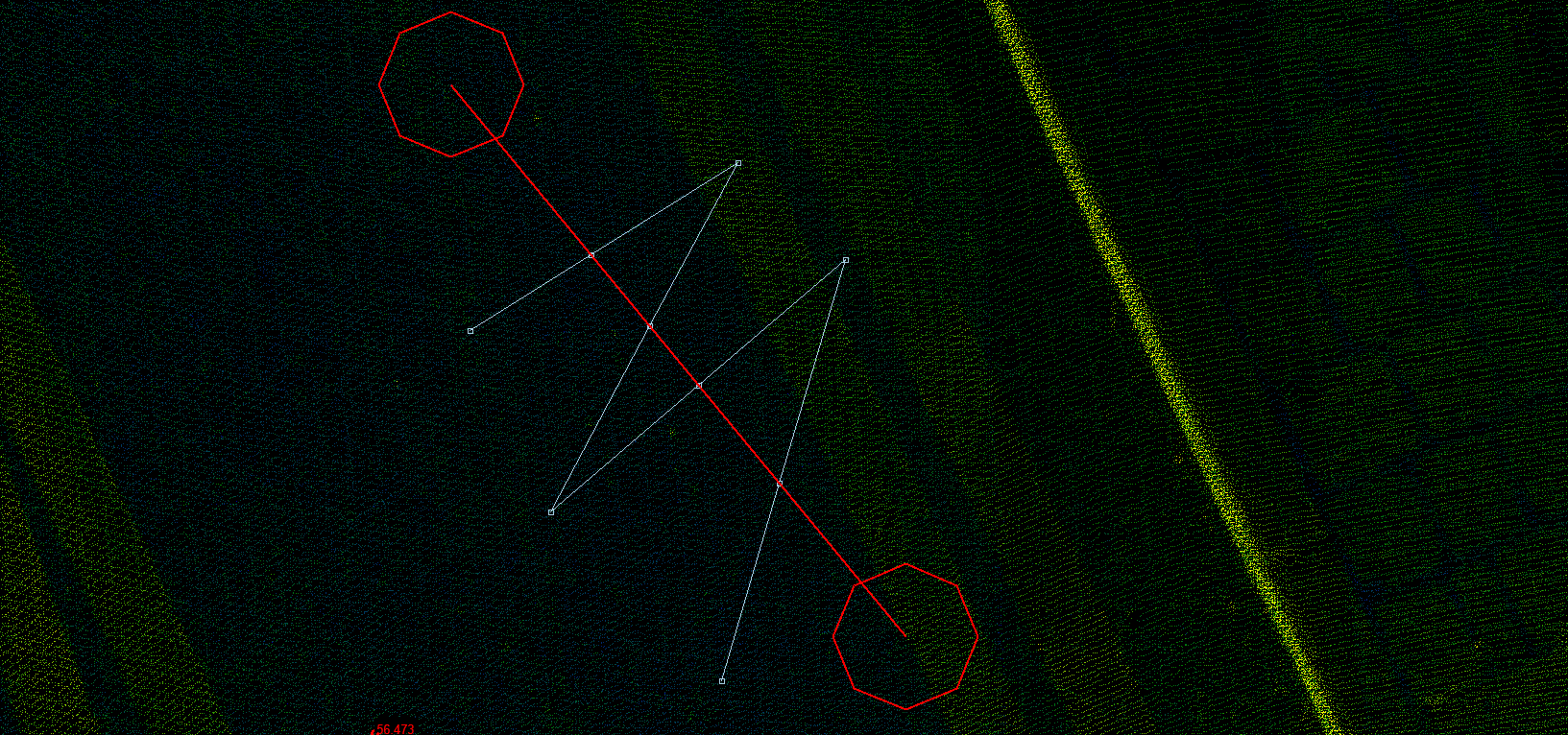
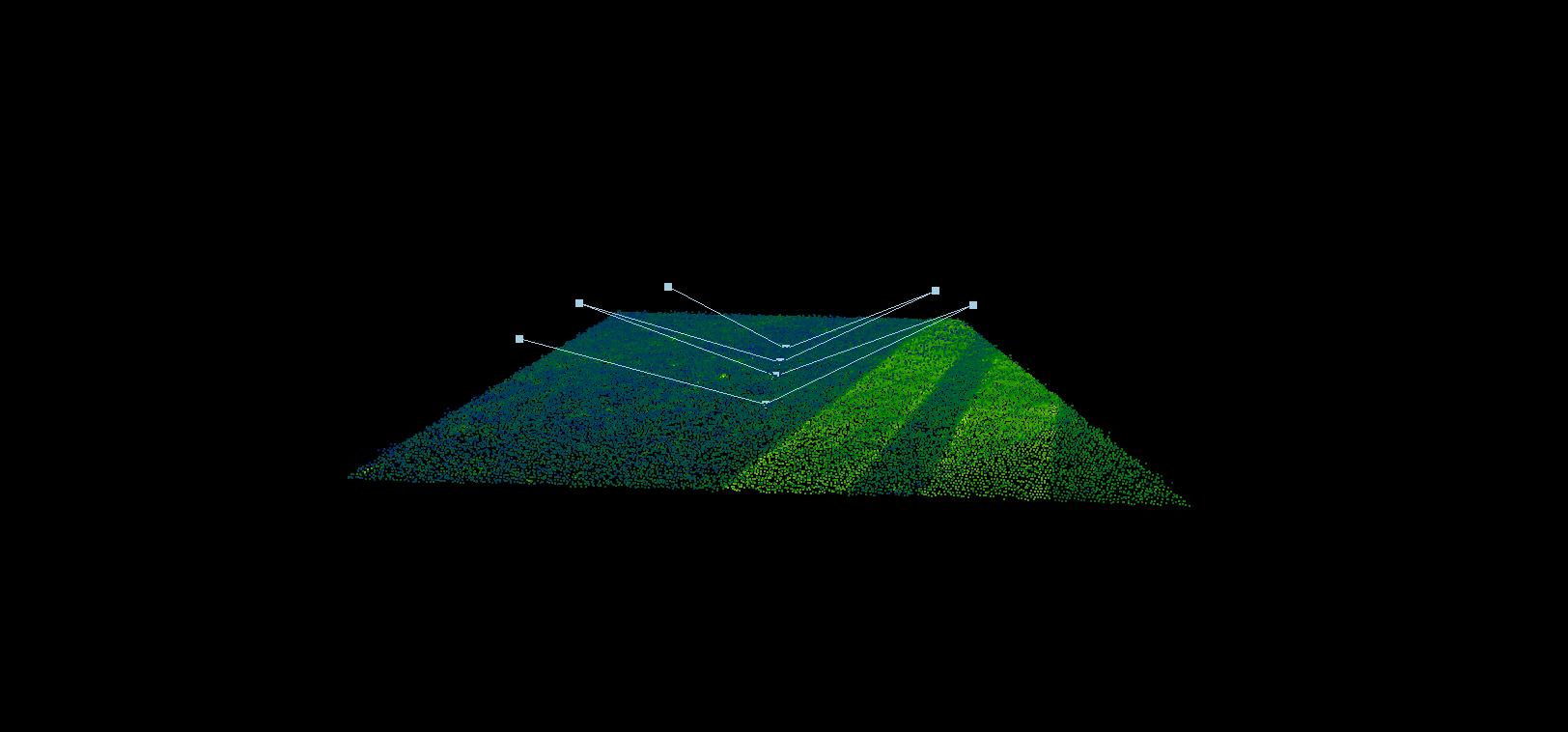
- Measured Line and Polyline/Polygon intersections - This tool allows users to draw a line in the 2D view, and where the line does intersect any polyline or polygon from the active SHP, a new vertex will be inserted. The tool allows the user to use all snap modes. The elevation of the new vertexes will be interpolated from the intersecting line. If the line that has to be intersected is above the ground, but the intersecting line is snapped to the cloud at the ground level, the new vertexes will be located at the ground level.
- Project point- This tool allows the user to select a baseline, and vertexes can be projected to the baseline. The tool can use any SHP file (point, polyline, polygon). The tool allows the user to use all snap modes. The tool can project points and polyline/polygon vertexes as well. After starting the tool, the user can adjust the settings for the tool:
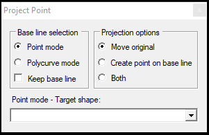
The settings are the following:
Base line selection - Point mode - The user can pick two points using any snap mode, which will define the baseline for the projection. Using this method enables the Target Shape dropdown.
Base line selection - Polycurve mode - The user can pick two neighbouring points in a polyline to serve as a baseline. Using this method disables the Target Shape dropdown.
Projection options - Move original - Move the original point/vertex to the baseline. This option may modify polylines/polygons upon vertex projection.
Projection options - Create point on baseline / Insert point on baseline - Create/insert a point to the baseline at the projected location. The function switch automatically based on the Base line selection.
Projection options - Both - The original point will be moved, and a new vertex will be created/inserted into the baseline.
Point mode - Target shape - Active only if the Base line selection is set to Point Mode. The user can select a point-type SHP, where the freshly created points will be stored.
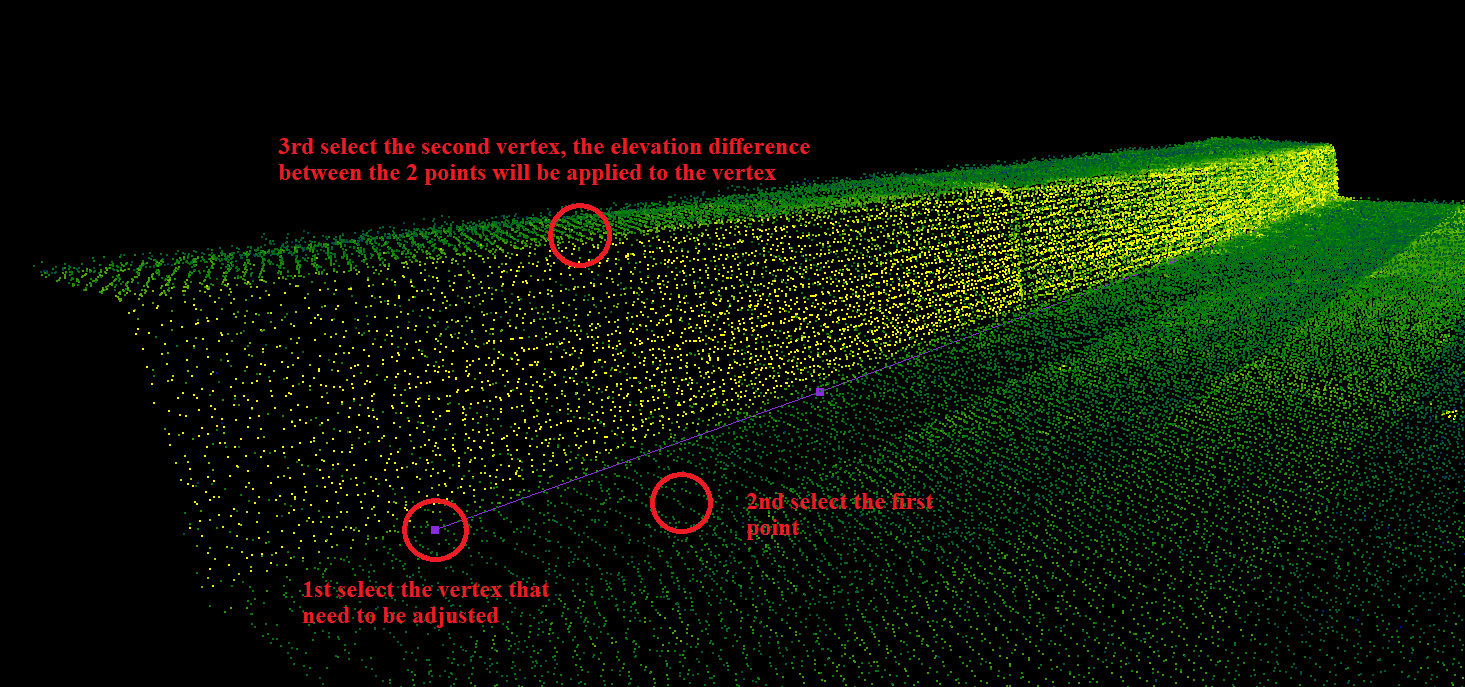
- 2 pt Z correction - This tool allows the users to select a vertex from the active SHP and specify an elevation difference using point cloud snap mode. The vertex's elevation will be updated with the specified elevation difference. The tool can raise or lower a vertex depending on whether the second selected vertex is lower or higher than the first one. After the elevation changes, the tool resets itself, and the user can pick a new vertex to adjust. Use right-click to close the tool or select a new vertex. Starting the tool will reset the active SHP selection.
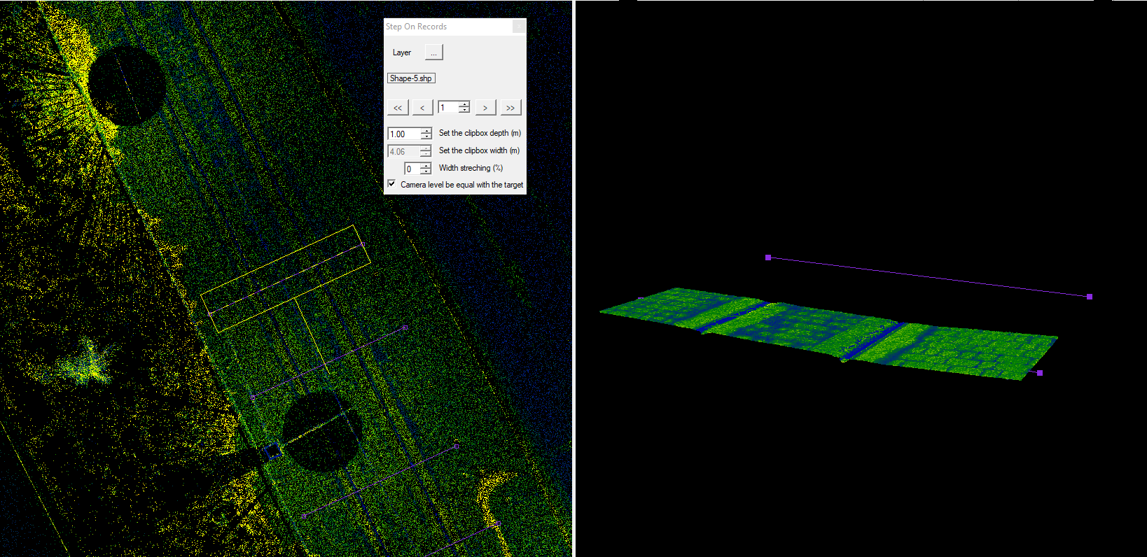
- Step on records - The Step on Records tool was initially designed to help the users check and adjust cross-sections in 3D by stepping record to record, but it can be utilised in other ways if the purpose of the checking is to check all records in an SHP file. This tool is above the standard tool logic, which means once it is started, the user cannot close it by right-clicking or pressing ESC, and other tools can run along. At the same time, the step on records is active, allowing the users to adjust the record's content while stepping in the records. The tool allows users to turn on the profile mode on the clip frame toolbar. After starting the tool, the settings window will open:
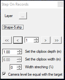
The settings are the following:
Layer - The user can pick a SHP file with the three dots. The tool can handle point, polyline and polygon SHP files as well. We strongly recommend checking the SHP before selecting it, as choosing an SHP which contains significant vectors might result in a 3D loading which is beyond the capabilities of PCS (for example, if the user selects a road edge polyline, which is 1 km long, and the source data is a Riegl MLS dataset, it might crash the software, as it will try to load the whole 1 km to 3D.) The most common use case is selecting a cross-section SHP or a point SHP. The SHP name will be written under the three-dot icon. This setting can be changed anytime, but when a new SHP is selected, the record counter will return to the first record. After selecting the SHP, the clip frame will automatically be adjusted to the first record, and the 3D view reloaded.
Record step - The arrows and the counter allow the user to jump to the first, previous, next or last record. The record number can be entered manually.
Set the clip box depth (m) / width (m) - The user can specify the clip frame depth and width. If the selected SHP is a point or polygon, the user can adjust both options. If the selected SHP is a polyline, the width will be locked to the exact length of the polyline, and only the depth can be changed.
Width stretching (%) - This setting allows the user to stretch the clip frame with a given % if there is a need to load a bigger area than the cross-section width. The same result can be achieved if the width is adjusted, but for polyline SHP, it is impossible.
Camera level should be equal with the target - The target SHP element will be centred for the 3D view camera.
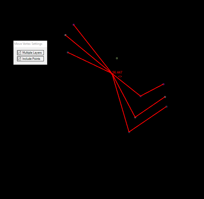
- Move Vertex in Multiple Layers - This tool allows the user to move vertexes on any SHP files, and if a vertex exists in multiple SHP files, the vertex will be moved on all SHP files. The snap modes will be locked vector snaps at the start. Free point and vector snaps are available after vertex(es) are selected. Starting the tool will also open the settings panel, where the user can select the Multiple Layers option, which is on by default and allows the user to move multiple vertexes at the same location from different SHP files. The included point checkbox allows the users to move the point SHP objects if they are snapped to the vertex along with polylines/polygons. If this option is not checked, the line and polygon vertexes will be moved, but the underlying point will not be. When the user selects the vertex, all connected polylines will turn red, indicating which objects will be adjusted.
- Rotate Point - This tool allows the users to rotate a point object, and the rotation will be stored in the selected rotation column (most commonly CadAngle attribute). This function is required for CAD extractions. The tool can be used for text and block (insert) rotation. The tool visualisation is effective mostly if the text labelling and the block display have been set. The tool can be started only with an active point SHP. After starting the tool, select the point which needs to be rotated. After selecting the vertex, the yellow support line appears, and another left click can set the new angle. As long as no right-click is pressed, the rotation can be changed continuously. The software will indicate the rotation in 2D view with a yellow indicator line, and the rotation angle (the angle measured from the start point, not the one which will be stored in the CAD Angle field) will be displayed. If the tool is in the rotation state, pressing the right-click will allow the user to select a new point. If the user is in a point selection state, pressing right-click will close the tool. Pressing ESC will terminate the tool.

- Rotate Shape - The tool allows users to rotate a polyline or polygon object with a base point. It can be used only for the active SHP. After starting the tool, the user can select a vector from the active SHP and then a base point around which the rotation will be performed. In a 2D view, an indicator will show the user the result of the rotation. The tool resets the active SHP selection. It is the same as rotating with a base point in any CAD software. The tool opens an additional window where the user can check the "Select 1st rotation point manually", allowing the user to use an additional basepoint for rotation.
- Modify Vertex XY - The tool allows users to adjust the selected vertex's location only in XY dimensions. After starting the tool, the user shall pick a vertex to modify; the snap mode will be locked to vector snap. After the vertex is selected, all snap modes are available for the user. The vertex can be continuously moved around until the user does not use the right-click. Even if the snap mode is set to point cloud snap, the vertex elevation will not be changed.
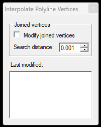
- Interpolate Polyline Vertices - This function allows the user to pick 2 points in a single polyline element, and all vertices between the selected 2 points will be lineary interpolated in terms of elevation. The joined verticies might be interpolated as well, if they are within the set interval.
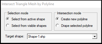
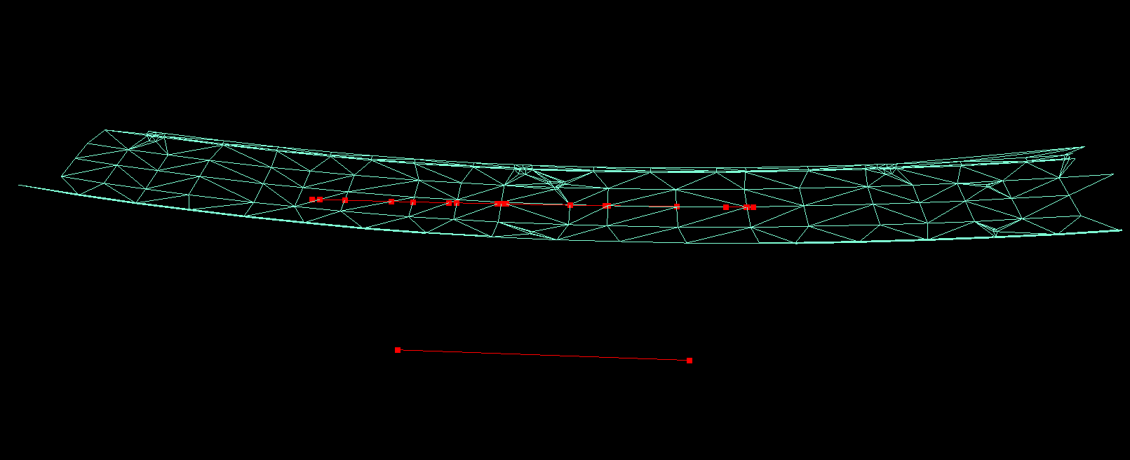
- Polyline Triangle Mesh Intersection - This function allows the users to drape one or more polylines from the active or visible SHP files to a generated TRI surface. After starting the tool, the settings panel will appear, where the user can select if the active or visible shapes shall be used and a new or existing polyline shall be draped to the TRI surface. The tool will insert a vertex to the result polyline everywhere where it intersects with the TRI surface.
- Point and Elevation label to SHP - This tool allows the users to annotate elevations for polyline and polygon elements in a new point (TEXT) SHP file, which will include the elevations. The generated file can be directly exported to CAD using the export functions described in the Extraction for CAD environments guide.
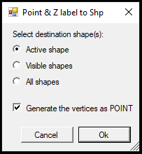
The user can select whether the active, visible or all SHP files should be considered for the tool. If the Generate the vertices as POINT option is selected, the TEXT and the POINT SHP are generated. If the linework, the text and the points are exported together to CAD, all polylines and polygons will receive points and elevation annotations for all vertices.
- Explode MultiGeometry - After starting the tool the user can select an SHP object, and if it is a MultiGeometry object - a MultiPolygon or MultiPolyline - it will be exploded to separate elements. All element will inherit the source object's attributes.