¶ Surface and contour generation
The surface and contour generation functionality in PCS allows the users to generate TIN surfaces based on point clouds and vectors and, from this surface, generate a contour SHP.
Before reading this guide further, please ensure you are familiar with the basic and advanced extraction guides. The vectors extracted during the advanced extraction guide will be used to generate the surface.
Before starting the surface building, it is recommended to have a 3D boundary of the target area. The TIN surface will include the boundary, which shall be extracted in 3D. If a 2D boundary is given, adjust the elevation using the Drape function from the Shape Toolbar.
Generating a surface within PCS is possible using the Triangulator. The TIN surface can be generated based on point clouds or vectors or combined. Before starting the triangulator, make sure that the drawing is topologically correct. This means all vertexes are snapped together, with no Z difference, no close non-snapped vertexes, and no 2D segment intersections. Topologically incorrect vectors may result in wrong surfaces, or the tool won't be able to complete the task. To check the topology, use the Topology Toolbar tools.
If a point cloud is being used for surface generation, make sure that the cloud has a significantly reduced density. Because of the nature of clouds, they contain way too many points to generate a usable surface from all points. If the purpose of the surface generation is a general surface, a few dozen points per square meter is enough. A few points per square meter is enough if a quick surface is required. Using all points from a point cloud is also possible, but it will drastically increase the processing time and triangle count, resulting in a surface that cannot be handled properly due to its size. The classification can also help generate a better surface if the cloud has a ground class, for example.
This article discusses two examples: reduced-density cloud surface and vector surface. The contour generation will be described afterwards.
¶ Surface - based on reduced density cloud
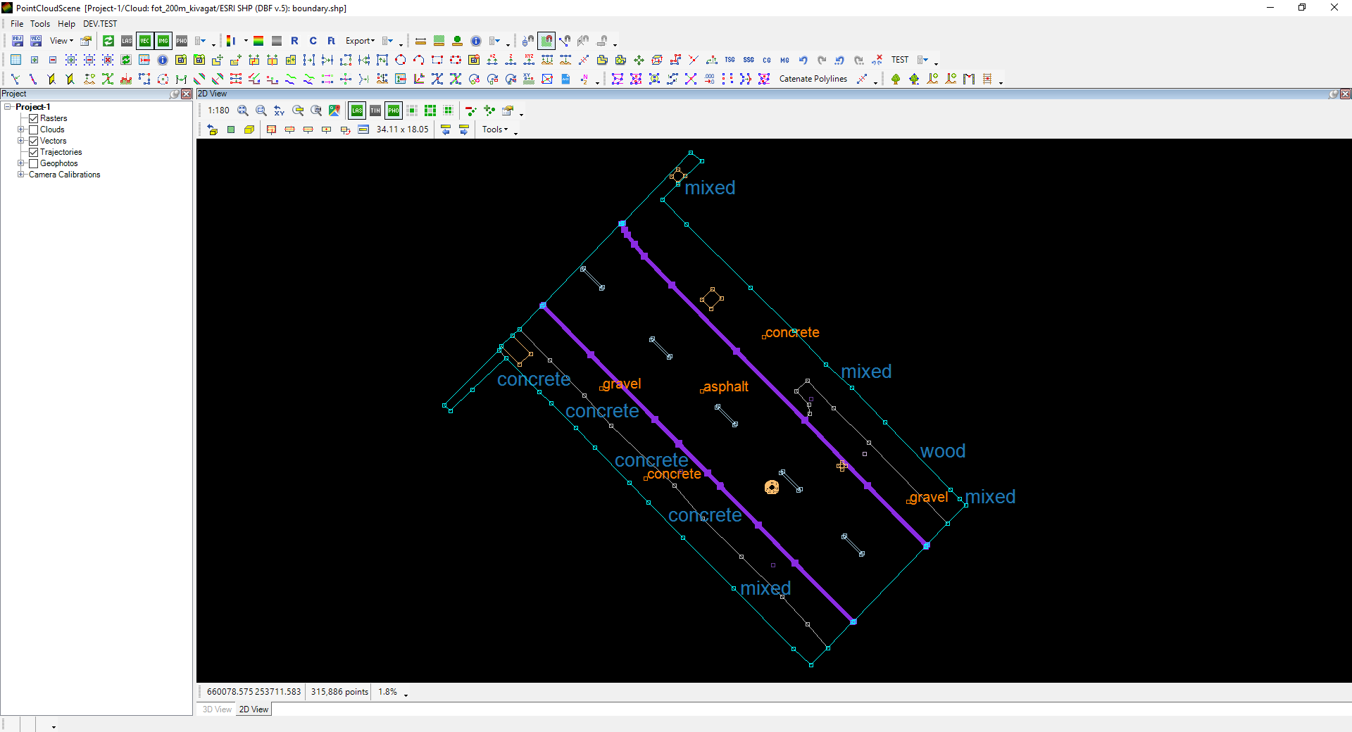
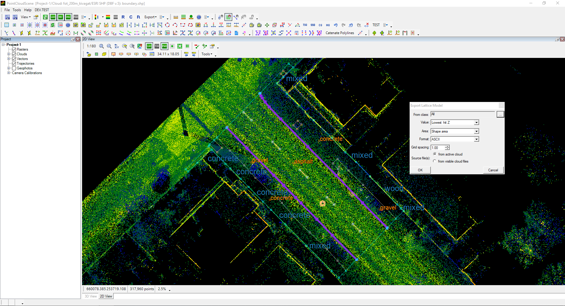
In this case, the cloud density shall be reduced. This can be reached using Project Explorer if the user right-clicks on the cloud file and selects the Reduce Density option. The other method - and one presented here - is to export a lattice from the cloud. This tool can be started from the Point Cloud toolbar - Export dropdown menu. In our example, the following settings will be used: 1 m grid from all classes within the boundary (the lowest hit Z value will be assigned for vertexes at the centre point of each 1x1 m grid).
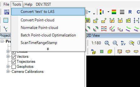
The software will prompt the user when the export has been finished and the txt file is generated. The next step is to create a point cloud from the text file, using the Tools menu - Convert 'text' to LAS function. This function can utilize the ASCII format; the conversion will fail if another format is selected during the lattice export.
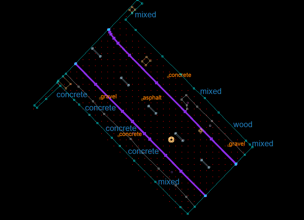
The generated LAS file is unoptimised, so before the first opening, optimize it or ensure that optimization is set in LAS settings at the File menu. The generated cloud will have no intensity value, so the Elevation or Default colour setting is the best for visualisation.
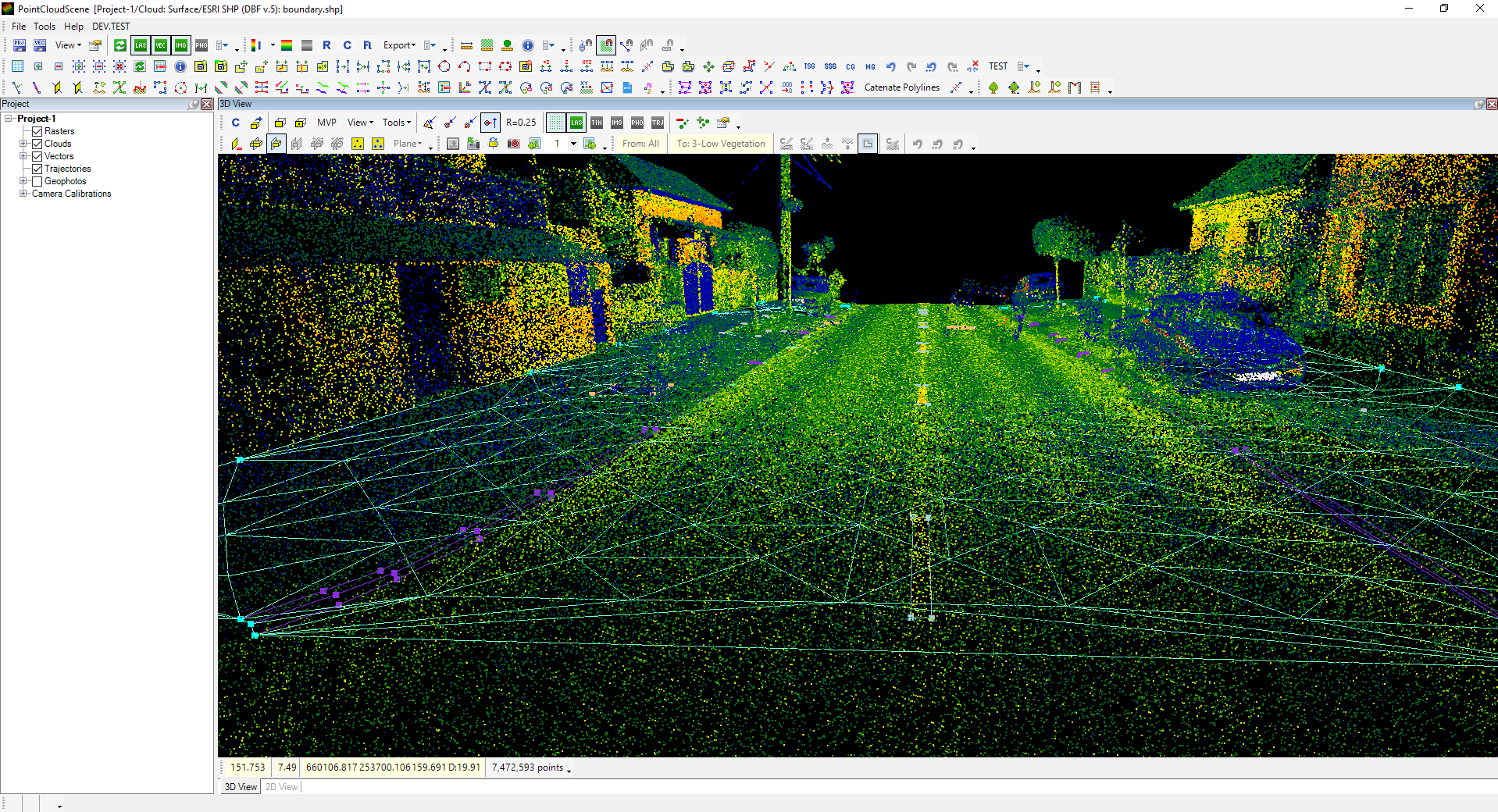
After the reduced-density cloud is created, the Triangulator can be started. Append the boundary to ensure the target area and the reduced-density cloud are covered.
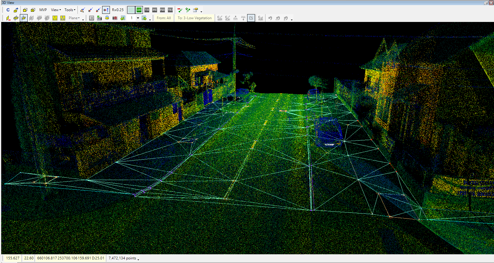
The software will perform the surface generation, and the TRI file will be generated. The triangles can be inspected in 2D and 3D views as well.
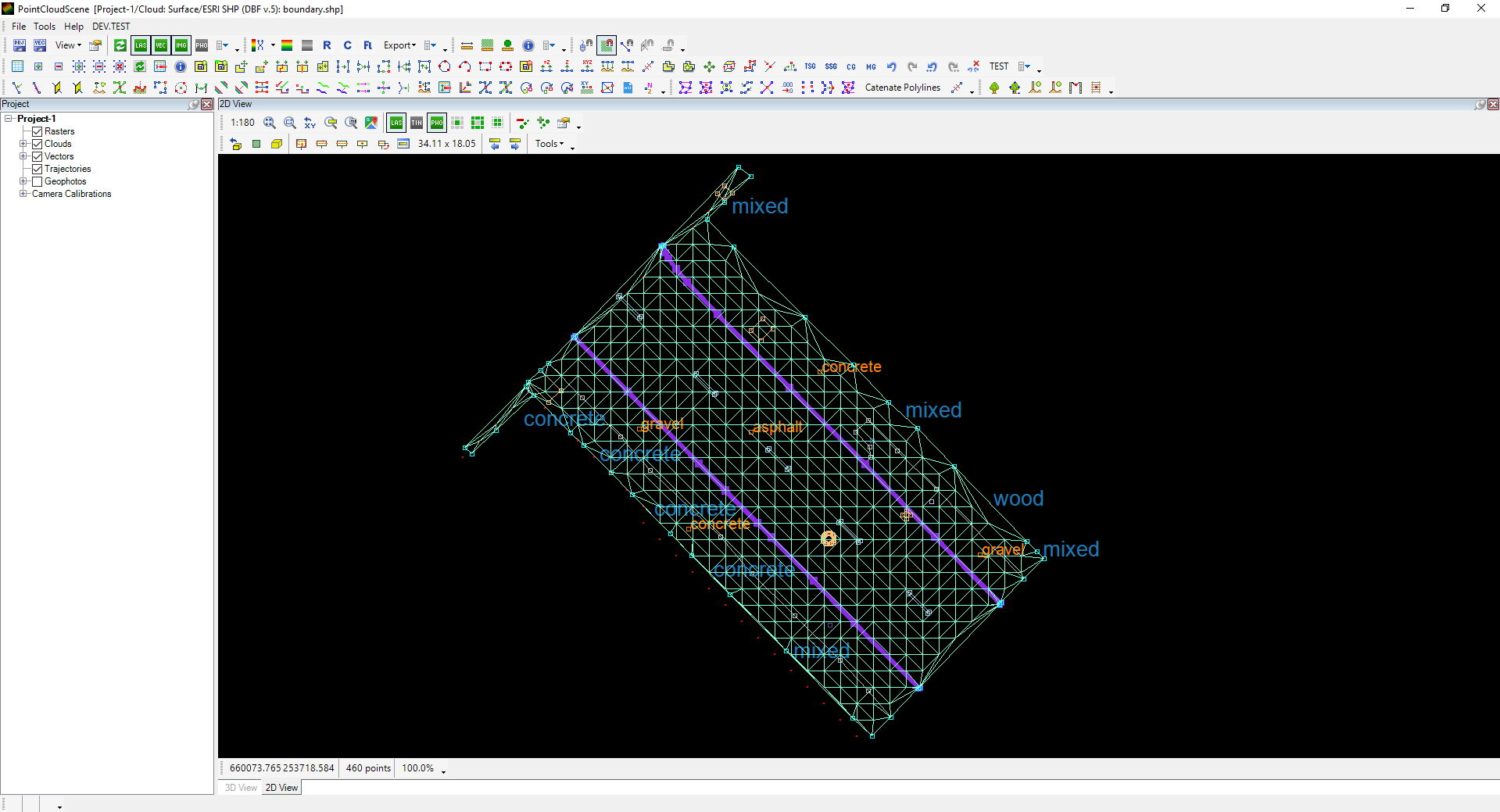
The surface can be used for various purposes within PCS or exported to SHP or DXF files. Without a surface, contour generation cannot be performed as well.
¶ Surface - based on vectors
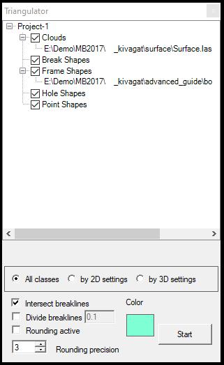
Surfaces can be generated purely based on vectors. As described above, the linework shall be topologically correct, and every line and point shall be in a proper 3D place to ensure the surface is valid. The process is the same as before, but when the triangulator is started, the following shall be selected:
- Break Shapes - Every polyline and polygon SHP in proper 3D shall be included. These lines will be used as break lines.
- Frame Shapes - The boundary shall be included here
- Hole Shapes - If a doughnut surface is created, insert the polygon SHP, which defines the inner part of the surface.
- Point Shapes - All point-type SHP, for example, texts, blocks and points, shall be included in the surface generation.
The generation will also provide a TRI file, but the clouds are ignored this time. The resulting surface is perfectly aligned with the vectors.
Please note that this surface only uses vectors, which means the surface might differ from the cloud in some places. This is usually acceptable, but consider the project specifications. Check our Surface-Cloud difference guide to check the difference between the surface and the cloud.
If needed, surface generation can also be combined with point clouds; append clouds - after the required preparation - to the Triangulator.
¶ Contour generation
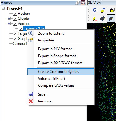
Let's move on to contour generation, as the user can now generate a surface from point clouds and vectors using the Triangulator. The process can be initiated by right-clicking the TRI file and selecting the Create Contour Polylines option. This tool can be started only if the TRI file is the active vector.
After selecting the tool, the settings panel will appear:
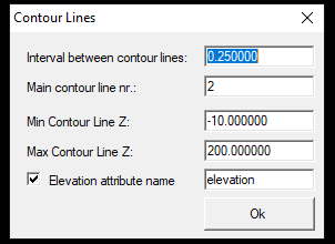
The settings are the following:
- Interval between contour lines - The main interval between two contour lines. Consider the area you are working with along with the project specification.
- Main contour line nr. - Every Nth line will receive a “Main” value for the Type attribute value and other contours will receive a “Base” value. This attribute is generated only if the Elevation attribute name checkbox is checked.
- Min/Max Contour Line Z - The contours will be generated within this elevation range. In that way, the user can specify only the required elevation range.
- Elevation attribute name - If selected, the generated polyline will contain the elevation as an attribute.
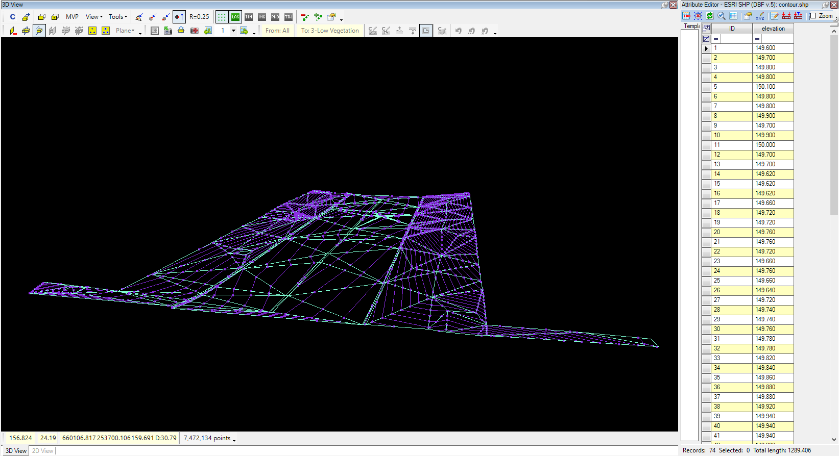
The generated contour lines will be placed in a new polyline SHP file. This file is not saved by default; the user shall save it if it is used later.
The generated contours can be utilized in other software, such as QGIS, or exported to CAD for further use. The Extraction for CAD Environments guide describes the export process for existing SHP files.